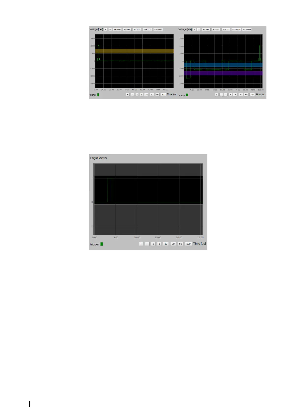
Sync and Mark trigger levels
In both figures the X axis is in microseconds and the Y axis is in millivolts.
Differential synchronization signals
Differential inputs are equipped with opt-isolated receivers which provide only logical levels
on their outputs. This causes the picture on the oscilloscope to look more like the picture on
a logical analyzer. The signal can be only 0 or 1. However, the picture can still be useful
because it provides information about pulse polarity and length.
There is no setting for trigger levels for differential signals. It is defined by the RS422 standard.
Each differential input is equipped with a 100 Ohm resistor which can be used for impedance
matching. Selecting the “100 Ohm termination” check box connects the 100 Ohm resistor to
a corresponding differential input.
Litton/Sperry synchronization signals
A Sync signal for Litton/Sperry is a simple differential pulse with negative polarity, so
everything from the differential synchronization signals is applicable to Litton/Sperry Sync.
Litton/Sperry Azimuth is also a differential signal but besides information about azimuth, it
also contains radar control related information (see the figure below). Even if the MK 6.0
Radar Interface box does not control the radar, it receives this information. For this reason,
Azimuth is not processed by the Azimuth block but is processed by the Alt block of the MK
6.0 Radar Interface box and the wire must be connected using the AL connector.
24
Settings | MK 6.0 Installation Manual