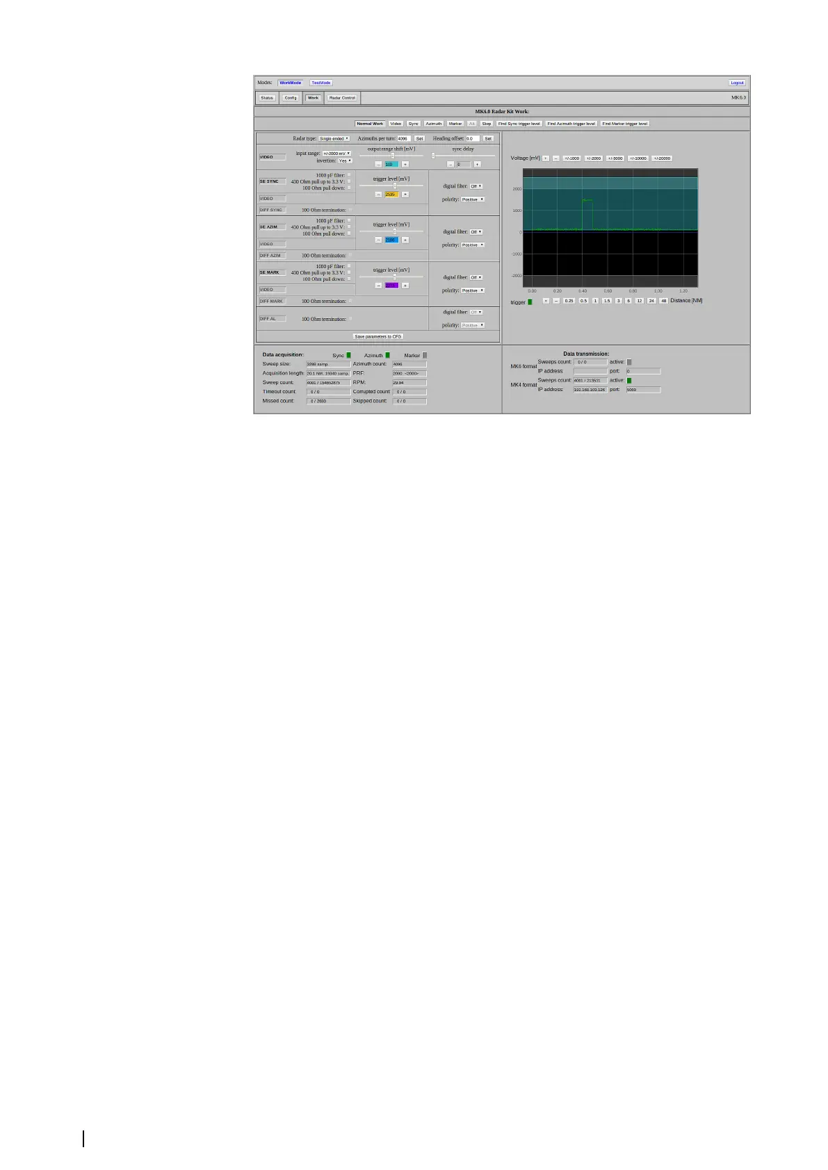
The Work page example
Radar type
One of the most important parameters on the Work page is the Radar type. The behavior of
the MK 6.0 Radar Interface box depends on the Radar type value. Each Radar type requires
specific synchronization signals: single-ended, differential or composite.
Video and synchronization inputs data is displayed at the left side of the Work page. Titles of
used inputs are black and unused are grey.
The Work page figure is an example of the single ended radar type settings with
synchronization signals from the "SE" (single-ended) connector with SYNC, AZIM and
MARK(ARP) inputs in use. Each input has a parameters set. The parameter settings are
independent for each particular input. In case an input is not in use, the parameter settings
are disabled.
The MK 6.0 Radar Interface box board supports several types of radars: Raytheon, Atlas,
Litton/Sperry, Radom, radars with differential synchronization signals and radars with single
ended synchronization signals. Connection of the synchronization signals is described in
"Synchronization signals" on page 10.
There are two other parameters close to the Radar type on the page. Their values depend on
the type of radar the MK 6.0 Radar Interface box is connected to. “Azimuth per turn” is the
number of azimuths, which the radars provide per one turn of the antenna. Various types of
radars provide various numbers of Azimuths per turn, but the MK 6.0 Radar Interface box
converts data to the 0..16384 range for azimuth. The corresponding setting in VarpPCI.ini is
ignored when the Extractor/Tracker application works with the MK 6.0 Radar Interface box.
“Heading offset” is the offset value between the antenna heading marker and the vessel
heading. Compensation of the heading offset is implemented in the MK 6.0 Radar Interface
box, so the Extractor/Tracker ignores the setting in VarpUniversal.ini when it receives data
from the MK 6.0 Radar Interface box.
Oscilloscope
The oscilloscope is used in all work modes. It provides the possibility to see various kinds of
signals which the MK 6.0 Radar Interface box acquires. The diagram data and coordinates
depend on the work modes. The X axis can be graduated in nautical miles (NM) or
microseconds (us). The Y axis can be graduated in millivolts or logical levels (0 and 1). Both
axis are available for scaling.
The figure shows the oscilloscope's screen while operating in the Normal Work submode.
The green oscillogram is the video signal. The black zone is the input video range. The grey
20
Settings | MK 6.0 Installation Manual