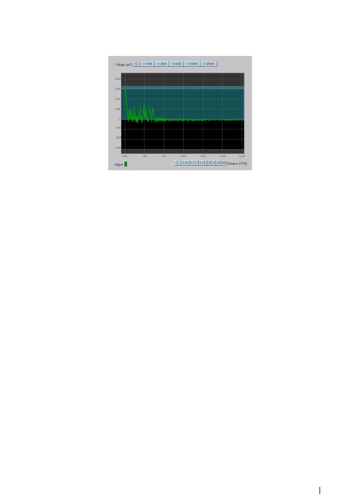
areas above and below are outside of the recommended limits. There can be distortion of
the signal in these areas. The blue line is the middle of the range and it corresponds to 0
level. The X axis is in NM and the Y axis is mV.
Oscilloscope functionality:
• “Dragging” - you can move the graph using the drag-and-drop method with the mouse.
• “Zooming” - When “Shift” key is pressed the zoom mode is active. In this mode a part of the
screen can be selected by the mouse to be zoomed. Zooming can also be changed using
the mouse wheel (regardless of the “Shift” key).
• Signal or distance range can be changed using the “+” and “-” buttons to increase and
decrease range two times.
• Double click on the oscilloscope pauses updating the screen.
• “trigger” indicator shows how the acquisition of the shown signal was triggered.
The "Trigger" indicator has the following color-coded statuses:
• GREY - there is no signal
• YELLOW - a signal exists, but it is not synchronized with the current synchronization signal.
• GREEN - the signal is synchronous with the synchronization signal.
For example, while operating in the Normal Work submode, the indicator can be grey or
green. In this case, the system requires synchronized signals only. However, while operating
in the “Video” submode, the indicator can also be yellow because the system also acquires
unsynchronized video if there is no synchronization. It allows tracing the video input when
there is no proper synchronization. When the system looks for the proper trigger level for
single-ended synchronization signals, the indicator is yellow in the beginning of the
procedure. Then when the proper level is found and the signal can be used to synchronize
itself, the indicator becomes green.
Normal work
When the “Normal Work” button at the top of the page is selected, the system works
normally and sends data to the Extractor/Tracker in the MK 6.0 Radar Interface box format.
Video data are sent to the Extractor/Tracker when operating in the “Normal Work” state only.
In all other states, signals are only displayed on the oscilloscope.
The video signal is synchronized by the current synchronization signal (depending on the
radar type). The indicators of synchronization (Sync, Azimuth and Marker) are blinking. In case
of synchronization signal loss, the video signal is also lost, and the oscilloscope diagram is
empty.
Video state
When the “Video” button at the top of the page is selected, the system acquires video but
does not send it to the Extractor/Tracker. The signal is displayed in the oscilloscope diagram
only for overseeing and analyzing. The signal is acquired and represented in linear format.
The acquisition length is fixed and is equal to 8128 samples. If there is a synchronization
signal, the video signal is synchronized with it. In case of synchronization signal loss, the
video signal is not synchronized and the sweep starts from a random moment. Sync/async
Settings | MK 6.0 Installation Manual
21