21
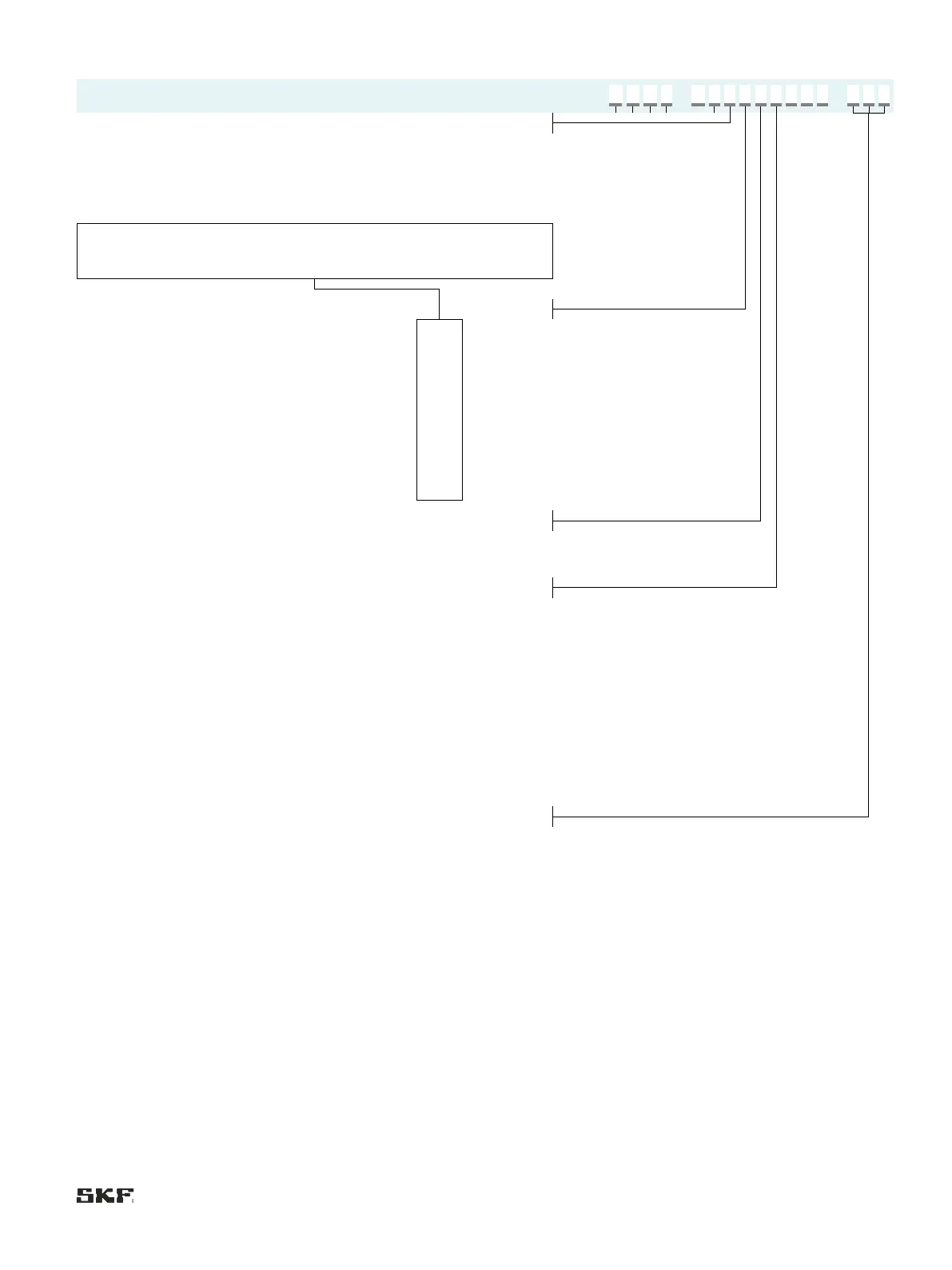
Without control unit, with
terminal strip
Without control unit, with
terminal strip and
pushbutton
NC contact (wire breakage
detection function)
NO contact (without wire
breakage detection)
Screwed gland;
1 rectangular connector
Circular connector M12×1;
1 rectangular connector
4)
1 plug; 1 rectangular
connector
50/60 Hz A, B, C, D, E
1)
If controls C–E are selected, only monitoring C can be selected.
2)
If control E is selected, only electrical connection 1 can be selected.
3)
Possible only with delivery rates 0.1 and 0.2 l/min.
4)
Only on design without control unit.
Order example:
• Gear pump unit for fluid grease
Lubricant level switch NC contact, pressure switch NO contact
• Delivery rate 0.1 l/min
• 2 liter plastic reservoir
• without control unit, with terminal strip
 Loading...


