Home
Skyjack
Boom Lifts
SJ46 AJ+
Skyjack SJ46 AJ+ Service Manual
4
of 1
of 1 rating
276 pages
Give review
Manual
Specs
To Next Page
To Next Page
To Previous Page
To Previous Page
Loading...
210
229042ABA
SJ46 AJ+, SJ46 AJ, SJ51 AJ
Section 5 – Procedures
Platform
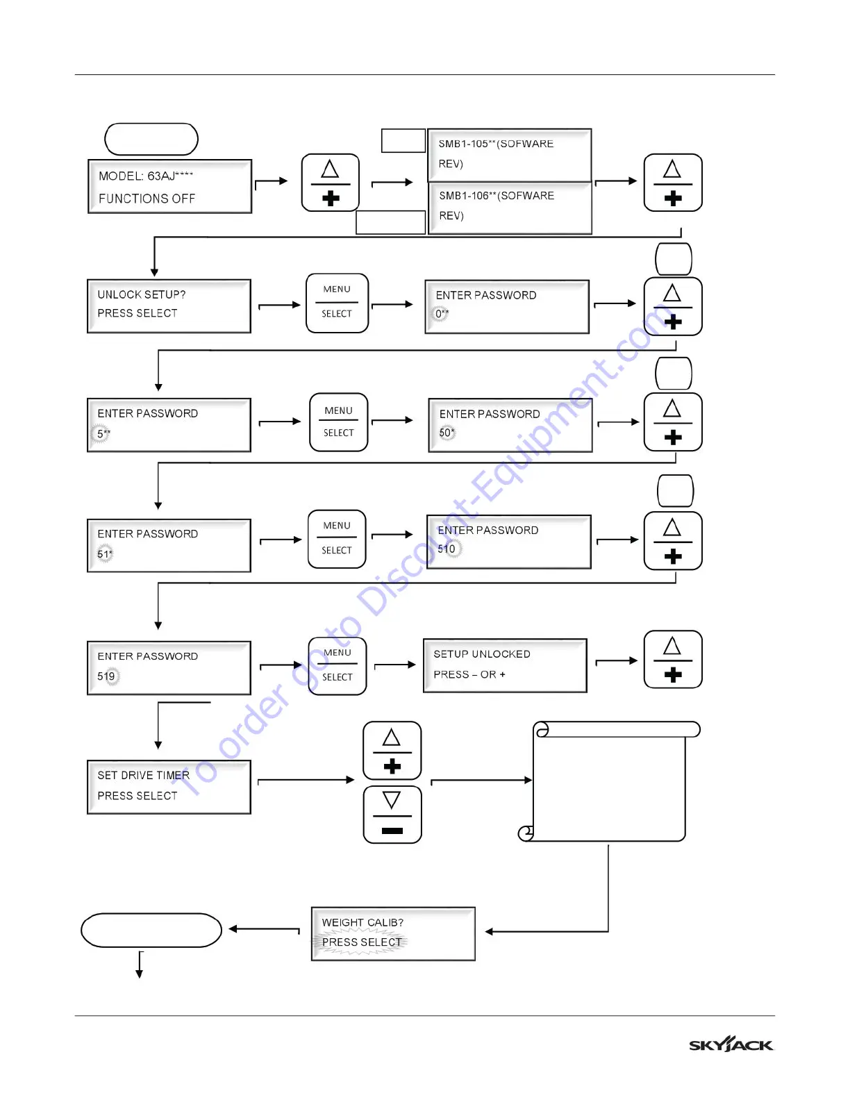
5.2-1
2
SCM C
alibrat
ion Fl
owchar
t - AN
SI/CSA
START SCREE
N
5X
1X
9X
Press
the + or - bu
tton until
you see th
e weig
ht calibratio
n
screen.
Continued
on the next
page
BASE
PLATFORM
To
order
go
to
Discount-Equipment.com
206
208
Table of Contents
Table of Contents
5
Section 1 - Scheduled Maintenance
13
Read and Heed
13
MEWP and Mobile Elevating Work Platform Definition
13
Purpose of Equipment
13
Use of Equipment
13
Manual
13
Service Policy and Warranty
13
Operator Safety Reminders, Warnings and Precautions
13
Maintenance and Service
14
Maintenance and Inspection Schedule
14
Owner's Annual Inspection Record
14
Replacement Parts
14
Maintenance and Service Safety Tips
14
Hydraulic System & Component Maintenance and Repair
15
Hydraulic Maintenance Hints
15
Railing Maintenance and Repair
16
Scheduled Maintenance
17
Service Bulletins
17
Maintenance and Inspection
17
Maintenance Instructions
17
Owner's Annual Inspection Record
18
Pre-Delivery/Maintenance Inspection Checklist
19
Scheduled Maintenance Inspections
20
Electrical
20
Hydraulic
20
Labels
20
Limit Switches
20
Engine Compartment
21
Control Compartment
24
Base
26
Platform
28
Boom Assembly
29
10 Optional Equipment
30
Function Tests
31
Section 2 - Maintenance Tables and Diagrams
32
Standard Hose Numbering System
32
Torque Specifications for Fasteners (US Imperial)
34
Torque Specifications for Fasteners (Metric)
35
Torque Specifications for Hydraulic Couplings & Hoses
36
MEWP Torque Specifications
37
Axle Torque Specifications
38
Axle Maintenance Intervals
39
Maximum Platform Capacity
40
Tire Specifications
40
Floor Loading Pressure
41
Hydraulic Specifications
42
Hydraulic & Gear Oils
43
Specifications & Features - Dimensions & Speeds
44
Engine Specifications
46
Reach & Dimension Diagrams - SJ46 AJ+ ANSI/CSA
47
Reach & Dimension Diagrams - SJ46 AJ CE & as
48
Reach & Dimension Diagrams - SJ51 AJ CE & as
49
Axle Oscillation Diagram
50
Section 3 - System Component Identification and Schematics
51
Electrical Symbol Chart
52
Hydraulic Symbol Chart
53
Wire Number and Color Code
54
Hydraulic Parts List
55
Electrical Parts List
58
Brake Manifold Components and Ports
61
Rotary Manifold Ports
62
Drive and System Pump Ports
63
Drive and System Pump Ports
64
Drive Motor Ports
65
Jib Valve Ports
66
Pressure Reducing Valve Ports
67
Main Manifold Ports
68
Generator Control Valve and Manifold
71
Main Harness and Fuel Level Switch Harness
72
Interface Harness - Deutz D2.9L
73
Interface Harness - Deutz D2011
74
Engine Interface Harness - Deutz D2.2
75
Interface Harness - Kubota
76
ECU Engine Wiring Diagram - Deutz D2011
77
Glow Plug Harnesses - Deutz D2.9L
78
Glow Plug Harnesses - Deutz D2011
79
Platform Harnesses
80
Platform Control Cables
81
Limit Switch Connections - ANSI/CSA
82
Limit Switch Connections - CE & as
83
Load Sensing Cable Connections - CE & as
84
All Motion Alarm Connections - CE & as
85
Flashing Amber Light Connections
86
SGE Wiring Diagram
87
Oil Cooler and 3.5 Kw Generator Base Control Box Wiring
88
Generator (3.5 Kw) Platform Control Box Wiring
89
Oil Cooler and 12 Kw Generator Base Control Box Wiring
90
Generator (12 Kw) Platform Control Box Wiring
91
12Kw Generator Electrical Connections
92
Load Circuit Wiring - no Generator
93
Load Circuit Wiring - 3.5 Kw Generator
94
Load Circuit Wiring - 7.5 or 12.5 Kw Generator
95
Hydraulic Schematic - ANSI/CSA
96
Hydraulic Schematic - CE & as
97
Platform Control Box Wiring - ANSI/CSA
98
Platform Control Box Wiring - CE
99
Platform Control Box Wiring - as
100
Base Control Box Wiring - ANSI/CSA
101
Base Control Box Wiring - ANSI/CSA with Positive Air Shut-Off Option
102
Base Control Box Wiring - CE Deutz D2.2
103
Base Control Box Wiring - CE Deutz D2011
104
Base Control Box Wiring - as
105
Electrical Schematic - ANSI/CSA
106
Electrical Schematic - CE with Deutz D2.2
107
Electrical Schematic - CE & as with D2011
108
Electrical Schematic - as
109
Interface & Engine Electrical Schematic - Deutz D2.9L
110
Interface & Engine Electrical Schematic - Deutz D2011
111
Engine Electrical Schematic - Deutz D2.2
112
Interface & Engine Electrical Schematic - Kubota WG2503
113
Section 4 - Troubleshooting Information
114
Introduction
114
Electrical System - ANSI/CSA
115
All Controls Are Inoperative from the Base or Platform Console
115
All Controls Are Inoperative from the Base Console
117
The Engine will Not Crank from the Base or Platform
117
The Engine will Not Crank from the Base
118
The Engine will Not Crank from the Platform
118
The Boom Controls Are Inoperative (Drive Operates)
118
No Boom up from the Base or Platform Controls
119
No Boom up from the Base Console
119
No Boom up from the Platform Console
119
10 No Boom down from the Base or Platform Consoles
119
11 No Boom down from the Base Console
120
12 No Boom down from the Platform Console
120
13 No Turret Rotate Right from the Base or Platform Consoles
120
14 No Turret Rotate Right from the Base Console
120
15 No Turret Rotate Right from the Platform Console
121
16 No Turret Rotate Left from the Base or Platform Consoles
121
17 No Turret Rotate Left from the Base Console
121
18 No Turret Rotate Left from the Platform Console
121
19 No Riser up from the Base or Platform Consoles
122
20 No Riser up from the Base Console
122
21 No Riser up from the Platform Console
122
22 No Riser down from the Base or Platform Consoles
122
23 No Riser down from the Base Console
123
24 No Riser down from the Platform Console
123
25 No Telescope out from the Base or Platform Consoles
123
26 No Telescope out from the Base Console
123
27 No Telescope out from the Platform Console
124
28 No Telescope in from the Base or Platform Consoles
124
29 No Telescope in from the Base Console
124
30 No Telescope in from the Platform Console
124
31 No Platform Level up from the Base or Platform Consoles
125
32 No Platform Level up from the Base Console
125
33 No Platform Level up from the Platform Console
125
34 No Platform Level down from the Base or Platform Consoles
125
35 No Platform Level down from the Base Console
126
36 No Platform Level down from the Platform Console
126
37 No Platform Rotate or Jib Functions from the Base or Platform Consoles
126
38 No Platform Rotate Right from the Base or Platform Consoles
127
39 No Platform Rotate Right from the Base Console
127
40 No Platform Rotate Right from the Platform Console
127
41 No Platform Rotate Left from the Base or Platform Consoles
128
42 No Platform Rotate Left from the Base Console
128
43 No Platform Rotate Left from the Platform Console
128
44 No Jib up from the Base or Platform Consoles
128
45 No Jib up from the Base Console
129
46 No Jib up from the Platform Console
129
47 No Jib down from the Base or Platform Consoles
129
48 No Jib down from the Base Console
129
49 No Jib down from the Platform Console
130
50 No Drive or Steer Functions
130
51 No Forward or Reverse Drive
130
52 No Forward Drive
130
53 No Reverse Drive
131
54 The Brake will Not Release
131
55 No Left Steer
131
56 No Right Steer
132
57 The Directon Sensing Is Inoperative
132
Weight
133
59 The Overload Indicator Light Does Not Turn on When the Platform Is Overloaded
133
60 The Audible Alarm Does Not Turn on with the Platform Overloaded
133
Electrical System - CE & as
134
All Controls Are Inoperative
134
No Power
135
Engine will Not Crank
136
Engine Cranks but will Not Start
140
Glow Plug Circuit Inoperative - Deutz D2011 Diesel Engine
143
All Base Control Console Inoperative
144
No Movement from Base Control Console
145
All Controls Inoperative from Platform Control Console
152
Throttle Inoperative, MID and High - Deutz D2.9L
164
10 MID Throttle Inoperative
165
11 High Throttle Inoperative
166
12 Brake will Not Release
167
13 Differential Lock will Not Engage
168
14 Differential Lock Engages Momentarily but will Not Stay Engaged
168
15 No Drive and Steer
169
16 No High Speed Drive
171
17 No Elevated Drive
173
18 Direction Sensing Inoperative
173
Load Sensing System - CE & as
175
Green Power LED Is Not Flashing
175
Load Cell Red Alarm LED Is on (with Platform Empty)
175
Red Error LED Is on
175
Load Cell Red Alarm LED Is off (with Platform Overloaded)
175
Platform Indicator Light Does Not Turn on
175
Audible Alarm Does Not Turn on
175
Boom and Drive Functions Are Enabled (with Boom Extended)
176
Hydraulic System
177
All Controls Inoperative
177
All Boom Functions Inoperative
177
No Main Boom up
177
No Main Boom down
178
No Riser Boom up
178
No Riser Boom down
179
Riser Boom down Jerky
179
No Turret Rotate Left
179
No Turret Rotate Right
180
10 No Boom Extend
181
11 No Boom Retract
181
12 No Jib up - ANSI/CSA
181
13 No Jib up - CE & as
182
14 No Jib down - ANSI/CSA
182
15 No Jib down - CE & as
183
16 No Platform Rotation Right - ANSI/CSA
183
17 No Platform Rotation Right - CE & as
184
18 No Platform Rotation Left - ANSI/CSA
184
19 No Platform Rotation Left - CE & as
185
20 Platform will Not Level down Manually
185
21 Platform will Not Level up Manually
186
22 Brake will Not Release
186
23 Brake will Not Engage
187
24 Differential Lock will Not Engage
187
25 No Drive Forward or Reverse
187
26 No Forward Drive
187
27 No Reverse Drive
188
28 No High Speed Drive
188
29 No Right Steer
188
30 No Left Steer
188
31 Axle will Not Oscillate
188
32 Axle will Not Lock
189
Section 5 - Procedures
190
General
190
Safety and Workmanship
190
Platform
191
Human Machine Interface (HMI) - CE & as
191
User Interface Keys
191
OCM Character Functions Charts
192
OCM Function Channel Names
192
OCM Operating Values Chart - CE & as
193
How to Select OCM Functionality - CE & as
194
How to View OCM Operation - CE & as
195
How to Unlock and Modify OCM Settings - CE & as
196
OCM Pin Reference
197
10 OCM Pin Voltage Reference - CE & as
203
11 SCM Calibration - ANSI/CSA
206
12 SCM Calibration Flowchart - ANSI/CSA
207
13 Fly Boom Switch Voltage References
209
14 Platform Controller Voltage References
210
Load Sensing System - CE & as
211
Load Sensing System
211
Verify Proper Operation of the Load Sensing System
212
Calibration of Load Sensing System (with "Teach In" Handset)
213
Boom
214
Check Wear Pads
214
Shim Wear Pads
214
Cable Carrier Repair
214
Rotary Actuator Bolt Torque Procedure
214
Master Cylinder Replacement
215
Limit Switch Locations - SJ46 AJ+ ANSI/CSA
216
Limit Switch Locations - SJ46 AJ & SJ51 AJ CE & as
217
Turret
218
Check and Replace the High Pressure Filter
218
Adjust the Turret Rotation Gear Backlash
218
Swing Drive Removal
219
Swing Drive Replacement
220
Check the Swing Drive Oil
220
Change the Swing Drive Oil
220
Check Rotation Bearing for Axial Wear
221
Turret Rotation Gear Bolt Torque Sequence
221
Electronic Tilt Switch Setup Procedure
222
10 Battery Replacement
224
Deutz Diesel Engines
225
Replace Engine Oil and Filter
225
Replace the Fuel Filter
226
Replace the Air Filter
226
Check the Engine Belt
226
Check the Oil Cooler (Deutz D2011 Only)
226
Deutz D2.9L Fault Codes
227
Hydraulic Tank
247
Hydraulic Oil Replacement
247
Hydraulic Filter Replacement
247
Kubota WG2503 Dual Fuel Engine
248
Engine Parameter Display (Kantrak 1700)
248
Kubota WG2503 Diagnostic Trouble Codes
249
ECU Pin Reference Chart (Kubota WG2503)
254
Fuse Box (Kubota WG2503)
255
MAP Sensor (Kubota WG2503)
256
IAT Sensor (Kubota WG2503)
256
ECT (Kubota WG2503)
257
TPS & Engine Speed (Kubota WG2503)
257
Fuel Temperature Sensor (Kubota WG2503)
258
10 Oil Pressure Sensor (Kubota WG2503)
258
Manifold and Hydraulic Pumps
259
Hydraulic Brake Pressure Adjustment
259
Hydraulic System Relief Valve Adjustment
260
Riser down Relief Valve Adjustment
260
Turret Rotate Relief Valve Adjustment
261
Platform Level Relief Valve Adjustment
261
Test Charge Pump Pressure on Drive Pump
262
Test Forward Drive Pressure on Drive Pump
262
Test Reverse Drive Pressure on Drive Pump
263
Axles
264
Change the Oil in the Axles
264
Check the Oil Level in the Torque Hubs
264
Change the Oil in the Torque Hubs
264
Check the Oil Level in the Axle Gearbox
265
Change the Oil in the Axle Gearbox
265
Oscillating Cylinder Bolt Replacement
266
Oscillating Cylinder Replacement
266
Bleed the Oscillating Axle Cylinders
268
Test the Oscillating Axle Cylinders
268
10 Pin Brake Adjustments
269
11 Brake Inspection
270
Grease Points
271
Grease the Turret Ring Gear
271
Grease the Turret Swing Drive
271
Grease the Axles
272
Grease the Drive Shaft
272
Options
273
Generator Troubleshooting
273
Generator Frequency/Voltage Check & Adjustment
274
Other manuals for Skyjack SJ46 AJ+
Operation Manual
115 pages
4
Based on 1 rating
Ask a question
Give review
Questions and Answers:
Need help?
Do you have a question about the Skyjack SJ46 AJ+ and is the answer not in the manual?
Ask a question
Skyjack SJ46 AJ+ Specifications
General
Brand
Skyjack
Model
SJ46 AJ+
Category
Boom Lifts
Language
English
Related product manuals
Skyjack SJ45 AJ+
120 pages
Skyjack SJ85 AJ
112 pages
Skyjack SJ63 AJ+
115 pages
Skyjack SJ60 AJ+
120 pages
Skyjack SJ45T
106 pages
Skyjack SJ40T
106 pages
Skyjack SJ46AJ
120 pages
Skyjack SJ45 T+
116 pages
Skyjack SJ66T
106 pages
Skyjack SJ 46A
85 pages
Skyjack SJ 3219
89 pages
Skyjack SJ-7027
216 pages