SJ519 TH 216939ADA
25
Control Functions Section 3 – Familiarization
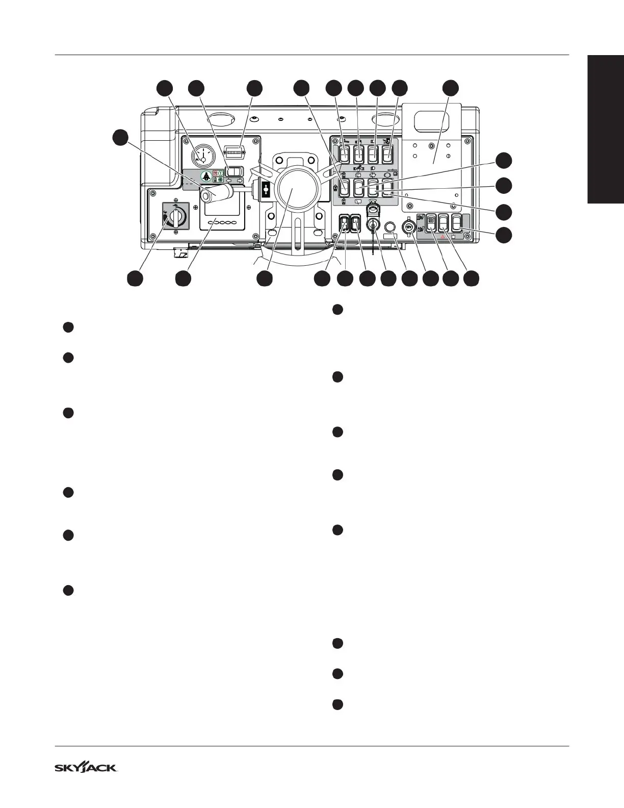
3.3-3 Operator’s Cab Dash Controls
1
Hourmeter: This gauge records accumulated
operating time of the telehandler.
2
Fuel Gauge: Indicates the amount of fuel in the
fuel tank. Fill the tank with ultra low sulfur diesel
fuel only when the indicator needle moves below
the 1/4 tank mark.
3
Direction Control Lever: This lever allows
forward or reverse travel. The center position
is neutral. To select forward travel, lift from lock
position and move the direction control lever to
the FWD position; for reverse travel move lever to
REV.
4
Hazard Warning Light Switch (If Equipped):
The hazard warning light switch activates all four
turn signals to indicate an emergency situation.
5
Left and Right Turn Signals Switch (If
Equipped): This rocker switch controls left and
right turn signals located on both the front and
rear of the telehandler.
6
Engine Data Display Module: Allows the
operator to select the required engine data such
as engine RPM, engine temperature, voltage,
and visualize it in the following formats:
▪
Analogue display
▪
Digital data
▪
Graphics
▪
Multi-data (a combination of the above)
▪
Current alarm messages
(Refer to Section 5.10 for details).
7
Steering Wheel/Tilt (If Equipped): Turn the
steering wheel to the left or right to steer the
telehandler in the corresponding direction. Three
steering modes are available (refer to Section
5.3).
8
Glow Plug Indicator: This light illuminates until
glow plugs have completed their timed cycle.
When the lamp goes out, the engine is ready to
be started.
9
Hydraulic Oil Temperature Indicator: This red
light indicator illuminates when the hydraulic oil
temperature is outside normal operating range.
10
Positive Air Shut-off Valve Indicator (If
Equipped): Illuminates red for a few seconds
when testing the functionality of positive air shut-
off valve.
11
Ignition Switch: This is a three position, anti-
restart switch.
▪
When in OFF position, it turns the engine off
and key can be removed.
▪
When in ON position, it provides power to
ignition and auxiliary circuits.
▪
When in START position, it starts the engine;
when released, key returns to ON position.
12
Horn Button: When depressed, the horn button
activates an audible warning.
13
12 Volt Power Port: A convenient 12 Volt power
port is located on the dashboard.
14
Attachment Hydraulic Flow Switch: Turns
hydraulic fluid flow to the attachment on and off.
P
FWD
REV
OFF
AUX
Flow
Direction
FWD
REV
2
3
6 7 118 9 10 12 41513
192021222324
16
14
17
18
15
25
FAMILIARIZATION