Installation
1.9
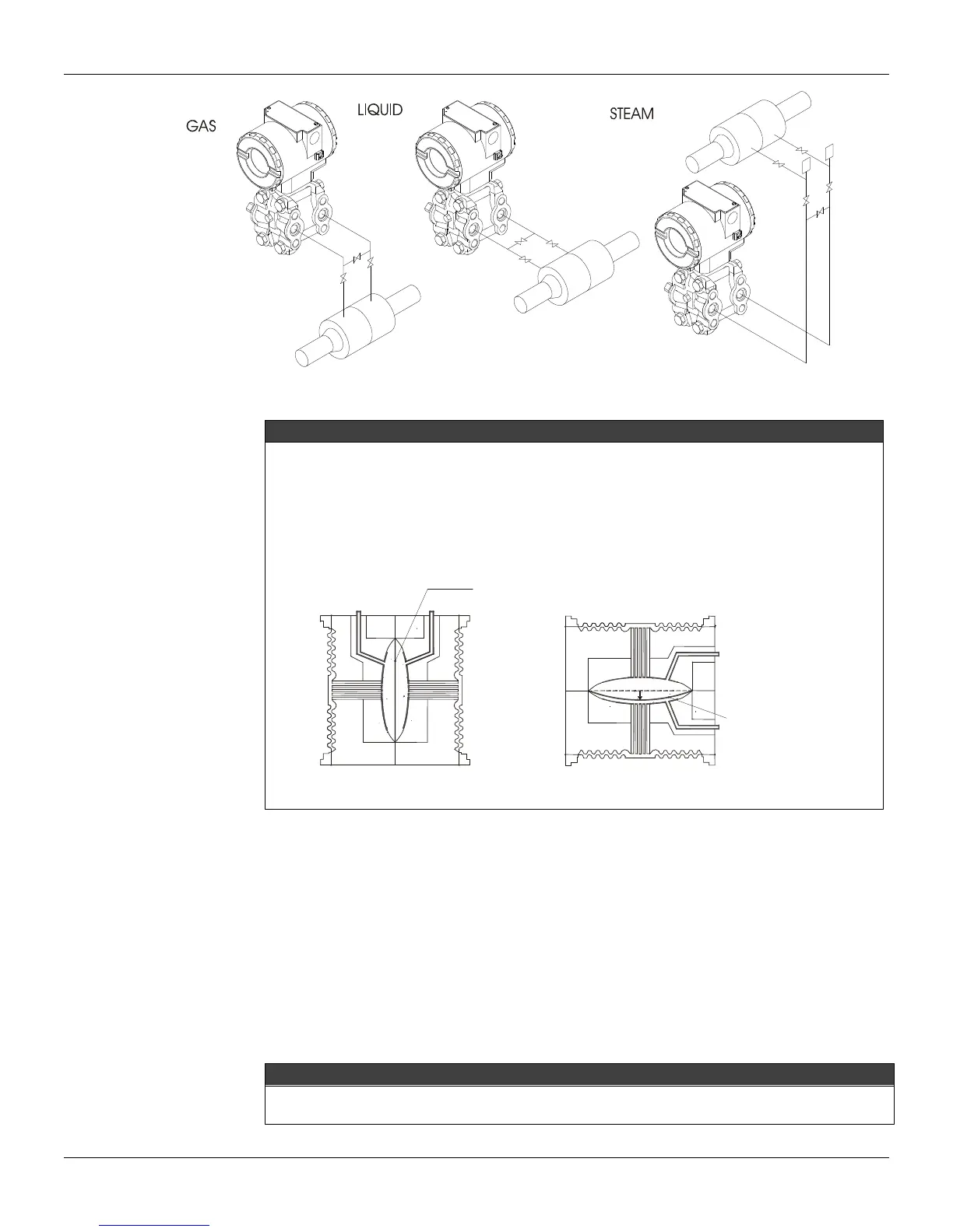
Figure 1.3 – Position of the Transmitter and Taps
NOTE
The transmitters are calibrated in the vertical position and a different mounting position displaces the
zero point. Consequently, the indicator will indicate a different value from the applied pressure. In
these conditions, it is recommended to do the zero pressure trim. The zero trim compensates the
final assembly position and its performance, when the transmitter is in its final position. When the
zero trim is executed, make sure the equalization valve is open and the wet leg levels are correct.
For the absolute pressure transmitter, the assembly effects correction should be done using the
Lower trim, due to the fact that the absolute zero is the reference for these transmitters, so there is
no need for a zero value for the Lower trim.
Electronic Housing
Humidity is fatal to electronic circuits. In areas subjected to high relative humidity, the O-rings for the
electronic housing covers must be correctly placed and the covers must be completely closed by tighten
them by hand until you feel the O-rings being compressed. Do not use tools to close the covers.
Removal of the electronics cover in the field should be reduced to the minimum necessary, since each
time it is removed; the circuits are exposed to the humidity.
The electronic circuit is protected by a humidity proof coating, but frequent exposures to humidity may
affect the protection provided. It is also important to keep the covers tightened in place. Every time they
are removed, the threads are exposed to corrosion, since painting cannot protect these parts. Sealing
methods should be employed on conduit entering the transmitter. The unused outlet connection should
be properly plugged.
WARNING
The unused cable entries should be plugged and sealed accordingly to avoid humidity entering, which
can cause the loss of the product’s warranty.
DIAPHRAGM SENSOR
SENSOR IN THE VERTICAL POSITION
SENSOR IN THE HORIZONTAL POSITION
HEAD OF THE FLUID
DIAPHRAGM SENSOR