LD301 - Operation and Maintenance Instruction Manual
5.6
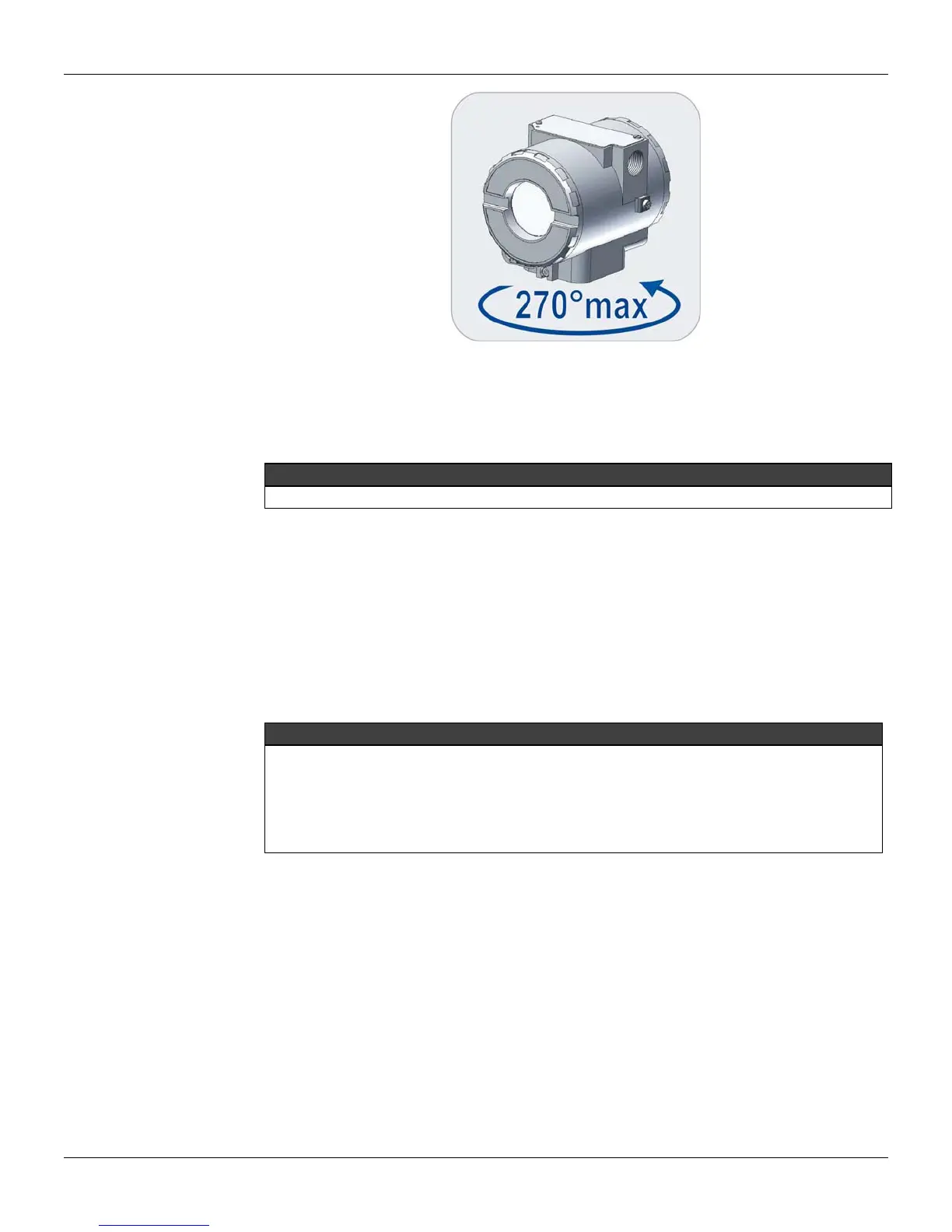
Figure 5.2 – Sensor Safety Rotation
Pull the main board out of the housing and disconnect the power supply and the sensor connectors.
Reassembly Procedure
WARNING
Do not assemble with power on.
Sensor
When mounting the sensor (27), make use of a new set of gaskets (19 & 20) compatible with the
process fluid. The bolts, nuts, flanges and other parts should be inspected for corrosion or other
eventual damage. Damaged parts should be replaced.
The O-rings should be lightly lubricated with silicon oil before they are fitted into place. Use halogen
grease on applications having inert filling fluid. The flanges must be positioned on a flat surface. Insert
the gaskets and Backup (28) (only for high pressure) in the flange according to figure 5.1. Set the four
bolts (18) and tighten the nuts (22) initially by hand while keeping the flanges parallel through the whole
mounting and finalize with an adequate tool.
O’RINGS AND BACKUP RINGS FOR HIGH PRESSURE
High pressure transmitters A5, A6, M5, M6 and High static pressure H2, H3, H4, H5 and the
sensors with tantalum diaphragm that use Buna-N or Viton O-ring must use a metallic backup Ring
(28) to prevent extrusion of O-ring. Do not use the backup O-Ring when using Teflon O-Rings or
flanges that have Kynar insets (PVDF).
Avoid bending the backup ring and inspect it for knits, cuts etc. Be careful when mounting it. The flat
side, which shines more than the beveled side, shall be mounted against the O-ring (Figure 5.3).
Procedure for tightening the flange screws
With the flanges holding the O-Rings in place, insert the four bolts (18) and tight the nuts (22) finger
tight, making sure the flanges remain parallel all the time.