Maintenance
5.7
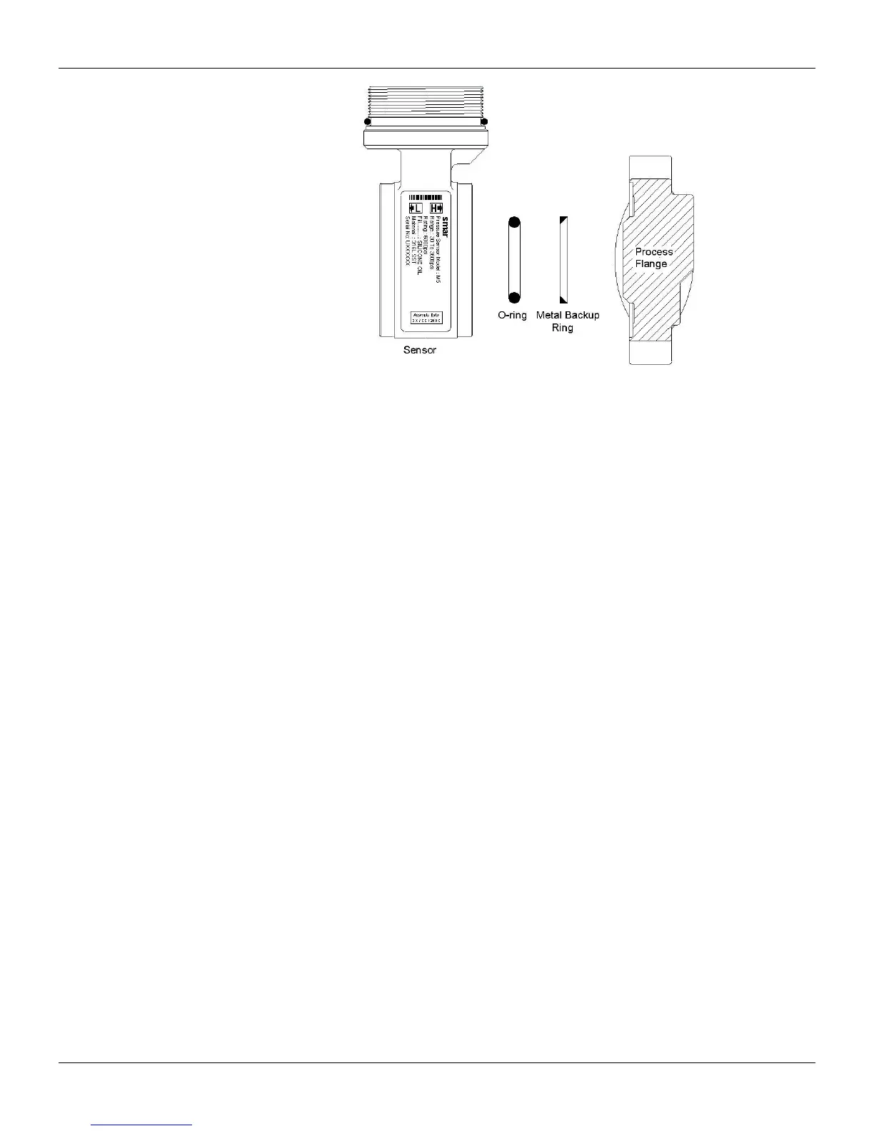
Figure 5.3 – Backup Ring Mounting
Tighten one nut till the flange seats;
Tighten the nut diagonally across with a torque of approximately 2.75 ±0.25 Kgf.m;
Tighten the first nut with the same torque;
Verify the flanges alignment;
Check torque on the four bolts.
Should the adapters (26) be removed, it is recommended to replace gaskets (24) and to connect the
adapters to the process flanges before coupling them to the sensor. Optimum torque is 2.75 ±0.25
Kgf.m.
The fitting of the sensor must be done with the main board out of the electronic housing. Mount the
sensor to the housing turning it clockwise until it stops. Then turn it counterclockwise until the cover (1)
is parallel to the process flange (17). Tighten the screw (8) to lock the body to the sensor.
Electronic Circuit
Plug sensor connector and power supply connector to main board. If there is a display, attach it to the
main board by means of 4 screws (3). The display can be installed in any of the 4 possible positions
(See Figure 5.4).
The ”” mark indicates up position.
Pass the screws (5) through the main board holes (6) and the spacers (7) as shown on Figure 5.1 and
tighten them to the body.
After tightening the protective cover (1), mounting procedure is complete. The transmitter is ready to be
energized and tested. It is recommended that adjustment be done on the ZERO TRIM and on the
UPPER PRESSURE TRIM.