LD301 – Operation and Maintenance Instruction Manual
2.2
Thus it is possible to conclude that the capacitive cell is a pressure sensor formed by two capacitors
whose capacitances vary according to the applied differential pressure.
Functional Description - Hardware
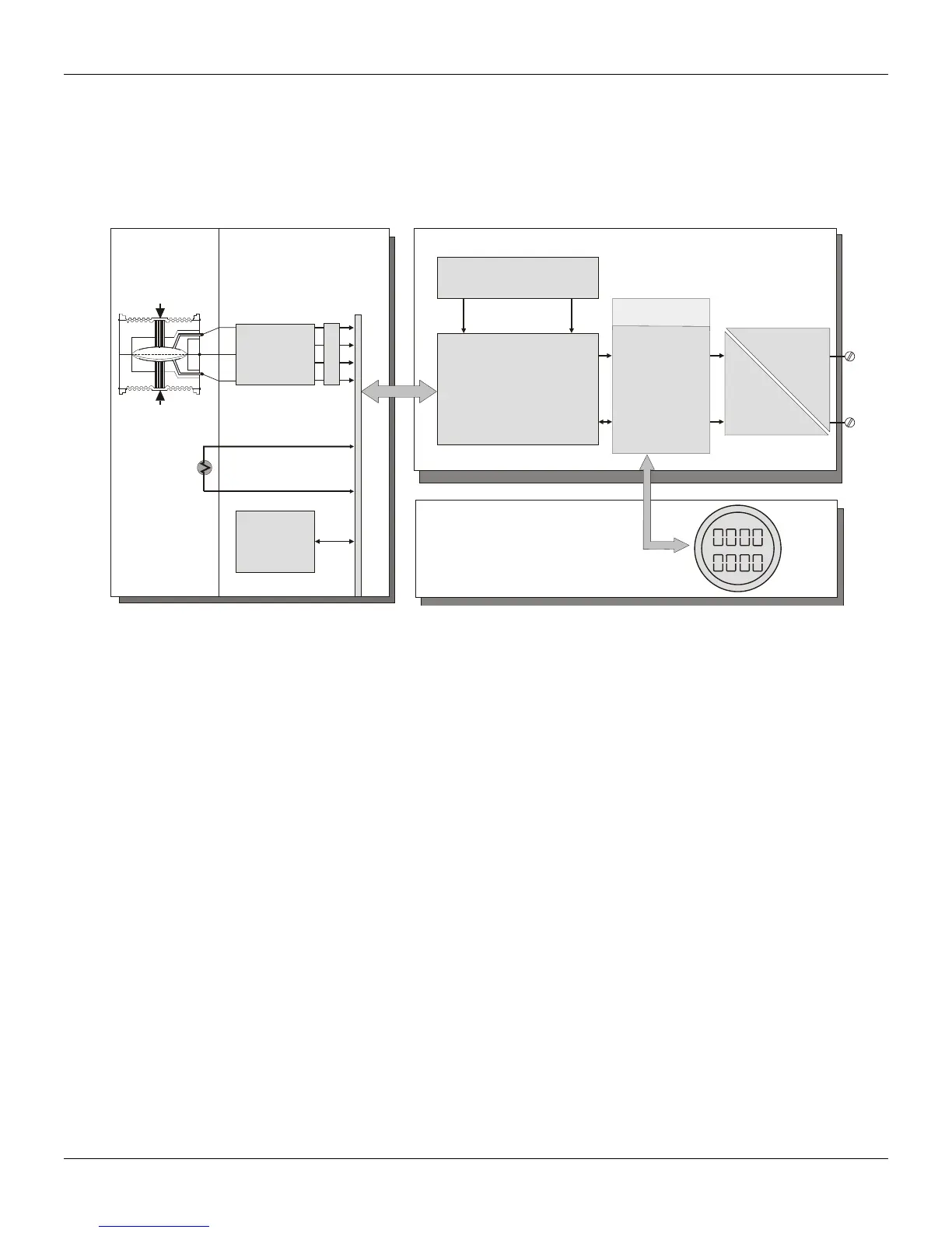
Refer to the block diagram Figure 2.2. The function of each block is described below.
P
H
P
L
HART
4-20 mA
HT3012
SENSOR
DIGITAL READING
IN
SULATOR
IN/OUT
OUTPUT
CONDITIONER
HART MODEM
D/A
CONVERTER
MATH
COPROCESSOR
DISPLAY
CONTROLLER
PROCESSING UNIT
RANGES
SPECIAL FUNCTIONS
PID
OUTPUT CONTROL
SERIAL COMUNICATION
PROTOCOL HART
LOCAL ADJUSTMENTS
ZERO / SPAN
DIGITAL
DISPLAY
ELECTRONIC
CONVERTER
CONVERTER
TEMPERATURE
ELECTRONIC
CONVERTER
PRESSURE
SENSOR
MAIN BOARD
Figure 2.2 – LD301 Block Diagram Hardware
Oscillator
This oscillator generates a frequency as a function of sensor capacitance.
Signal Isolator
The Control signals from the CPU are transferred through optical couplers, and the signal from the
oscillator is transferred through a transformer.
Central Processing Unit (CPU) and PROM
The CPU is the intelligent portion of the transmitter, being responsible for the management and
operation of all other blocks, linearization and communication.
The program is stored in an external PROM. For temporary storage of data the CPU has an internal
RAM. The data in the RAM is lost, if the power is switched off, although the CPU also has an internal
nonvolatile EEPROM where data that must be retained is stored. Examples of such data are:
calibration, configuration and identification data.
EEPROM
Another EEPROM is located within the sensor assembly. It contains data pertaining to the sensor's
characteristics at different pressures and temperatures. This characterization is done for each sensor at
the factory.
D/A Converter
It converts the digital data from the CPU to an analog signal with 14-bits resolution.
Output
It controls the current in the line feeding the transmitters.
It acts as a variable resistive load whose value depends on the voltage from the D/A converter.
Modem
This system provides the data exchanged between the serve-master digital communications. The
transmitter demodulates information from the current line, and after treating it adequately, modulates
over the line the answer to be sent. A "1" is represented by 1200 Hz and "0" by 2200 Hz. The frequency
signal is symmetrical and does not affect the DC-level of the 4-20 mA signal.