Section 2
2.1
OPERATION
Functional Description - Sensor
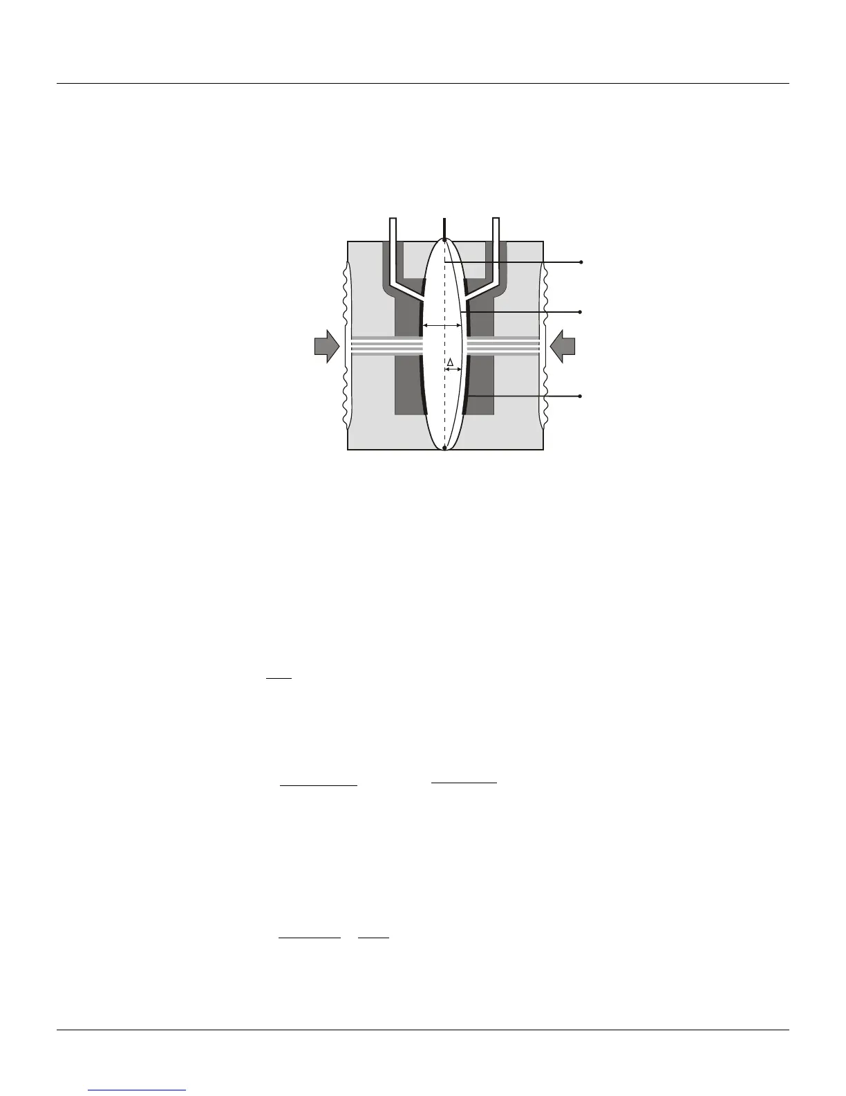
The LD301 Series Intelligent Pressure Transmitters use capacitive sensors (capacitive cells) as
pressure sensing elements, as shown in Figure 2.1.
SENSOR DIAPHRAGM
POSITION, WHEN P1=P2
SENSOR DIAPHRAGM
FIXED PLATES OF THE
H
P2P1
L
d
d
Figure 2.1 – Capacitive Cell
Where,
P
1
and P
2
are the pressures in chambers H and L.
CH = capacitance between the fixed plate on P
1
side and the sensing diaphragm.
CL = capacitance between the fixed plate on the P
2
side and the sensing diaphragm.
d = distance between CH and CL fixed plates.
∆d = sensing diaphragm's deflection due to the differential pressure ∆P = P
1
- P
2
.
Knowing that the capacitance of a capacitor with flat, parallel plates may be expressed as a function of
plate area (A) and distance (d) between the plates as:
Where,
∈= dielectric constant of the medium between the capacitor's plates.
Should CH and CL be considered as capacitances of flat and parallel plates with identical areas, then:
However, should the differential pressure (∆P) apply to the capacitive cell not deflect the sensing
diaphragm beyond d/4, it is possible to assume ∆P as proportional to ∆d, that is:
∆P is proportional ∆d.
By developing the expression (CL - CH)/(CL + CH), it follows that:
As the distance (d) between the fixed plates CH and CL is constant, it is possible to conclude that the
expression (CL - CH)/(CL + CH) is proportional to ∆d and, therefore, to the differential pressure to be
measured.
dd
A
CL
∆−
∈
=
)2/(
.
dd
CH
∆+
=
)2/(