LD301 - Operation and Maintenance Instruction Manual
4.2
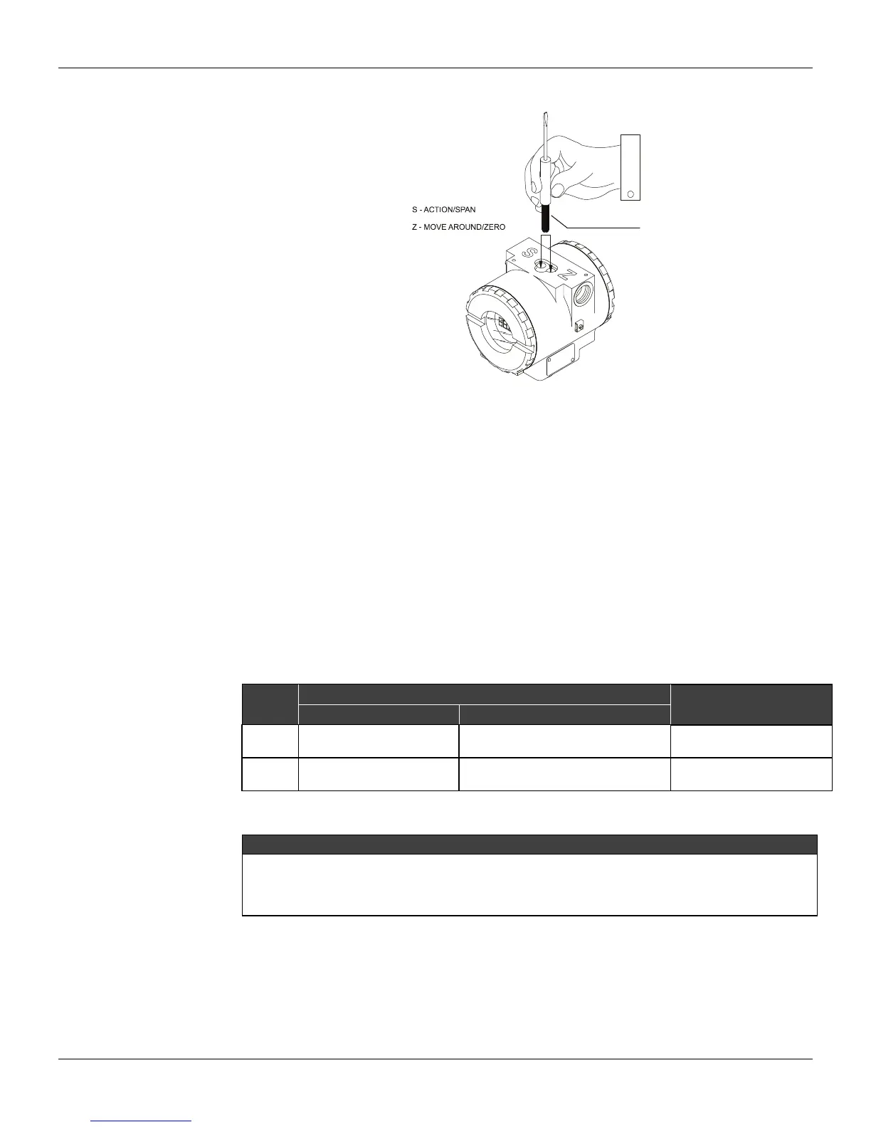
The transmitter has, under the identification plate, holes for two magnetic switches activated by the
magnetic tool (See Figure 4.2).
Figure 4.2 – Local Zero and Span Adjustment holes and Local Adjustment Switches
The holes are marked with Z (Zero) and S (Span) and from now on will be designated simply by (Z) and
(S), respectively. Table 4.2 shows the action performed by the magnetic tool while inserted in (Z) and
(S) in accordance with the selected adjustment type.
Browsing the functions and their branches works as follows:
1 - Inserting the handle of the magnetic tool in (Z), the transmitter passes from the normal
measurement state to the transmitter configuration state. The transmitter software automatically
starts to display the available functions in a cyclic routine. The group of functions displayed
depends on the mode selected for the LD301, either Transmitter or Controller.
2 - In order to reach the desired option, browse the options, wait until they are displayed and move the
magnetic tool from (Z) to (S). Refer to Figure 4.3 – Local Adjustment Programming Tree, in order to
know the position of the desired option. By placing the magnetic tool once again in (Z), it is possible
to browse other options within this new branch.
3 - The procedure to reach the desired option is similar to the one described on the previous item, for
the whole hierarchical level of the programming tree.
ACTION
SIMPLE LOCAL ADJUSTMENT
COMPLETE LOCAL
ADJUSTMENT
TRANSMITTER MODE CONTROLLER MODE
Z
Selects the Lower Range
Value
OPERATION and TOTAL
Moves among all the
options
S
Selects the Upper Range
Value
Activates the selected Functions
Functions
Table 4.2 - Local Adjustment Description
For LD301 versions prior to a V6.00, the digital display shall be number 214 - 0108 as per spare
parts list for LD301 V5.XX.
For LD301 versions V6.XX, the digital display shall be number 400-0559, as per the updated spare
Simple Local Adjust
The LD301 works differently when a simple local adjustment is selected in the transmitter mode and in
the controller mode. In the transmitter mode, the simple local adjustment is used for Zero and Span
calibration, and in the controller mode, it restricts the use of the configuration tree to the OPERATION
and TOTALIZATION functions.