LD301 – Operation and Maintenance Instruction Manual
2.6
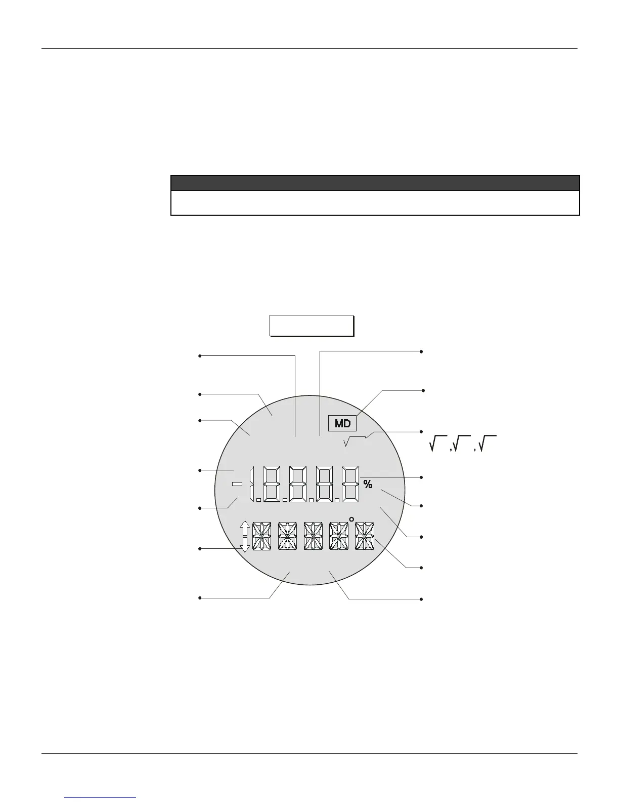
The Display
The local indicator is able to display one or two variables, which are user-selected. When two variables
are chosen, the display will alternate between both with an interval of 3 seconds.
The liquid crystal display includes a field with 4 ½ numeric digits, a field with 5 alphanumeric digits and
an information field, as shown on Figure 2.4.
When the totalization is displayed, the most significant part appears in the unit and function field
(upper) and the least significant part in the variable field (lower). See Total Value in Section 3.
Monitoring
During normal operation, the LD301 is in the monitoring mode. In this mode, indication alternates
between the primary and the secondary variable as configured by the user. See Figure. 2.5. The
display indicates engineering units, values and parameters simultaneously with most status indicators.
The monitoring mode is interrupted when the user does complete local adjustment.
The LCD may also display errors and other messages (See table 2.1).
M
A
Fix
F(t)
PID
SP
F(x)
35
PV
min
3 5
INDICATES THAT TOTALIZATION
IS DISPLAYED
INDICATES ACTIVE
TABLE FUNCTION
* PID IS OPTIONAL
INDICATES ACTIVE
MULTIDROP MODE
INDICATES ACTIVE FUNCTION
VARIABLE FIELD
UNIT PERCENT
UNIT MINUTES
UNIT AND FUNCTION FIELD
UNIT AND FUNCTION FIELD
VARIABLE IS NOW DISPLAYED
x x x
INDICATES TRANSMITTER
IN PID MODE*
INDICATES ACTIVE
CONSTANT OUTPUT MODE
INDICATES CONTROLLER
IN AUTOMATIC*
INDICATES CONTROLLER
IN MANUAL*
INDICATES POSSIBILITY
TO ADJUST / CHANGE
VARIABLE / MODE
INDICATES THAT
THE SETPOINT
IS NOW DISPLAYED
Figure 2.4 – Display
DISPLAY V6.00
The display controller, from release V6.00 on is integral part to the main board. Please observe the
new spare part codes.