Installation
1.11
CORRECT
WIRES
INCORRECT
Figure 1.6 - Conduit Installation
Loop Connections
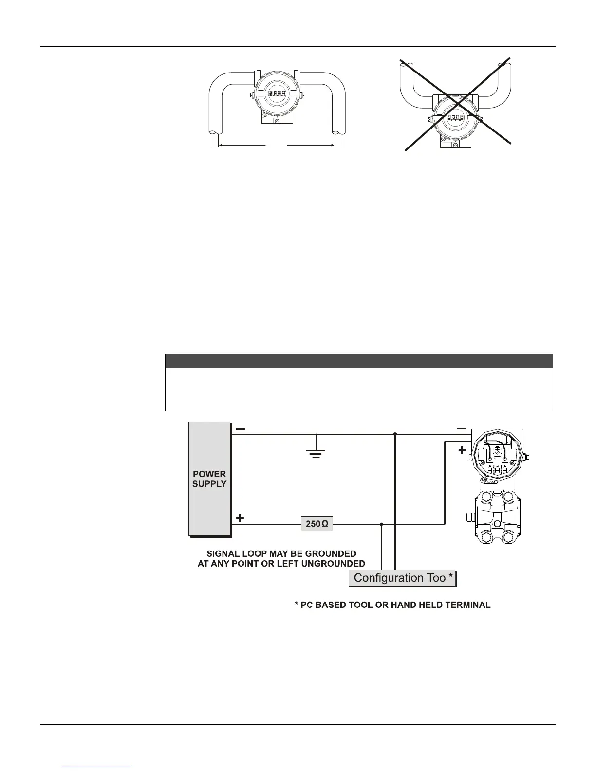
Figures 1.7 and 1.8 show LD301’s wiring diagrams to work as transmitter and controller, respectively.
Figure 1.9 shows the LD301’s wiring diagrams to work in the multi-drop network. Note that a maximum
of 15 transmitters can be connected on the same line and that they should be connected in parallel.
Take care to the power supply as well, when many transmitters are connected on the same line. The
current through the 250 Ohm resistor will be high causing a high voltage drop. Therefore make sure that
the power supply voltage is sufficient.
The Hand-Held Terminal can be connected to the communication terminals of the transmitter or at any
point of the signal line by using the alligator clips. It is also recommended to ground the shield of
shielded cables at only one end. The ungrounded end must be carefully isolated. On multi-drop
connections, the circuit loop integrity must be assured, with special care to prevent short-circuit between
the circuit loop and the housing.
NOTE
For HART transmitters to operate in multi-drop mode each transmitter must be configured with a
different identity Device ID. In addition, if the transmitter identification mode on the loop is done
through the Command 0 address, the HART address must also be different. If it is done through the
(Command 11) Tag the Tags must be similar.
Figure 1.7 - Wiring Diagram for the LD301 Working as a Transmitter