LD301 - Operation and Maintenance Instruction Manual
5.10
NOTE
( 1 ) For category A, it is recommended to keep, in stock, 25 parts installed for each set, and
20 for category B.
( 2 ) Includes Terminal Block, Screws, caps and Identification plate without certification.
( 3 ) O-rings and Backup Rings are packaged in packs of 12 units, except for spring loaded.
( 4 ) To specify sensors, use the following tables.
( 5 ) Including U-Clamp, nuts, bolts and washers
( 6 ) For this type, O-Ring pack has 1 piece.
Smar Insulator Kit
The Insulator Kit Smar prevents the generation of galvanic current between metals when in contact. The
difference of potential between the metals generates this current that flows from the metal with higher
potential to the metal with lower potential. This process in the presence of aqueous solution with salts,
acids or bases can start the corrosion process, where the corroded metal is always the one with bigger
potential (anode).
In the processes, when it is impossible to isolate the two potencialized metals, occurs the generation of
galvanic current. This current will form free ions of hydrogen (H
+
) in one of the solutions, with tendency
to start the corrosion and the migration of the Hydrogen to the diaphragm of the Remote Seal or of the
Level Transmitter.
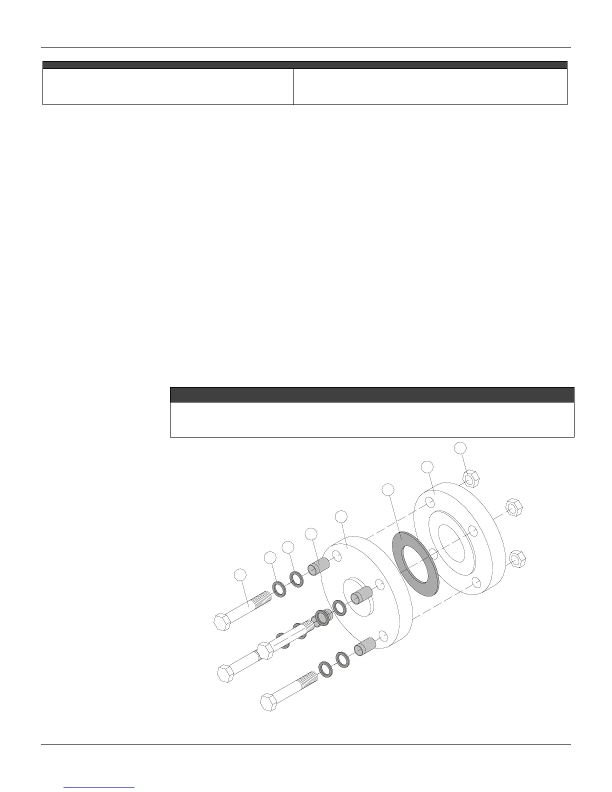
The figure 5.5 shows the following parts that constitute the Smar Insulator Kit: Teflon Gasket (6),
Nonmetallic Insulating Sleeve (4), Mica Washers (3) and Steel Washers (2).
Smar Insulator Kit Mounting
Mounting step by step:
1 – Insert all the Nonmetallic Insulating Sleeve (4) in the holes of the Sealed Flange (5);
2 – Put the Teflon Gasket (6) between the Flanges (5 e 7);
3 – Insert the Steel Washers (2) and the Mica Washers (3) in the bolts (1)
4 – Join the Flanges positioning its holes (5 and 7);
5 – Introduce the bolts in the holes of the flanges (5 and 7) and tighten the flanges with the nuts (8)
6 – Measure the resistance between the Sealed Flange (5) and the Flange of Process (7) that should be
tending to the infinite to check the efficiency of the Insulator Kit.
NOTE
If the studs are used instead of the bolts, obey the same mounting sequence for the items 2, 3 and 4.
This Insulator Kit can be applied with raised and flat face flanges.
The Gasket must be made of Teflon when the Smar Insulator Kit is indicated.
1
2
3
4
5
6
7
8
1
2
3
4
5
6
7
Nuts
Nonmetallic Isolating Sleeve
Sealing Gasket in Teflon
Process Flange
Sealed Flange
Steel Washer
Mica Washer
Bolt
8
Figure 5.5 – Insulator Kit Mounting