LD301 – Operation and Maintenance Instruction Manual
1.10
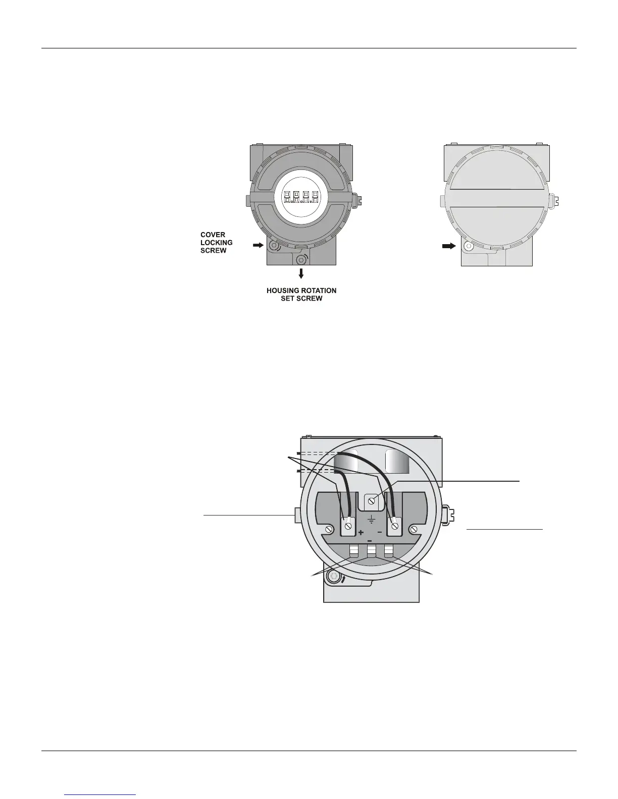
The electronic housing can be rotated to adjust the digital display on a better position. To rotate it, loose
the Housing Rotation Set Screw, see Figure 1.4 (a). To prevent humidity entering, the electric housing
and the sensor joint must have a minimum of 6 fully engaged threads. The provided joint allows 1 extra
turn to adjust the position of the display window by rotating the housing clockwise. If the thread reaches
the end before the desired position, then rotate the housing counterclockwise, but not more than one
thread turn. Transmitters have a stopper that restricts housing rotation to one turn. See Section 5,
Figure 5.2.
COVER
LOCKING
SCREW
(a) (b)
Figure 1.4 - Cover Locking and Housing Rotating Set Screw (a) Electronic Board Side
(b) Terminal Connection Side
Wiring
To access the wiring block, loosen the cover locking screw to release the cover. See Figure 1.4 (b).
Test and Communication terminals allow, respectively, to measure the current in the 4 - 20 mA loop,
without opening the circuit, and also to communicate with the transmitter. The “Test Terminals” must be
used to measure the current. The “COMM” terminal must be used for HART communication. The
terminal block has screws where fork or ring-type terminals can be fastened. See Figure 1.5.
POWER
SUPPLY
TERMINALS
AND HART
BUS
COMUNICATIONS
TERMINALS
LOCK
TEST
COMM
+
TEST
TERMINALS
®
OPTIONAL GROUND
TERMINAL
INTERNAL GROUND
TERMINAL
GROUND TERMINA
Figure 1.5 – Terminal Block
The LD301 is protected against reverse polarity.
For convenience there are three ground terminals: one inside the cover and two external, located close
to the conduit inlets.
Use of twisted pair (22 AWG or greater than) cables is recommended. For sites with high
electromagnetic levels (EMI above 10 V/m) shield conductors are recommended.
Avoid routing signal wiring near to power cables or switching equipment.
The Figure 1.6 shows the correct conduit installation, to avoid penetration of water or other substance,
which may cause equipment malfunction.