Configuration
3.15
Equipment Maintenance
Here are grouped maintenance services related with the collection of information required for equipment
maintenance. The following services are available: Order Code, Serial Number, Operation Counter and
Backup/Restore.
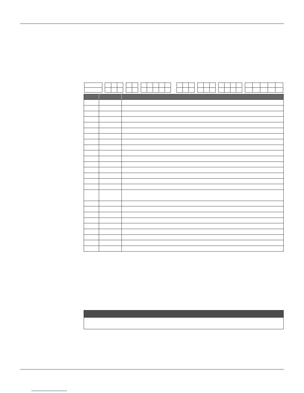
ORDER CODE - The Order Code is the one used for purchasing the equipment, in accordance with
the User specification. There are 26 characters available in the LD301 to define this code.
EXAMPLE:
# OPTION DESCRIPTION
1 LD301
Differential, Flow, and Level Transmitter.
2 D2
Differential, Range: -50 a 50 kPa.
3 1
Stainless Steel 316L Diaphragm and Fill Fluid with Silicone Oil.
4 0
Class of Standard performance.
5 H
HART® Transmitter 4-20 mA.
6 1
SIS: Safety Integrity System.
7 I
Flanges, Adapters, and 316 Stainless steal Drain/Vent valves.
8 B
Buna N O-Rings.
9 U
Drain in up position.
10 0
Process Connection: 1/4 - 18 NPT (Without Adapter).
11 0
Without Special Cleaning.
12 P
Flanges, nuts, and bolts Material: Plated Carbon Steel.
13 0
Flange Threaded for accessories fixing (adapters, manifolds, etc): 7/16” UNF.
14 2
With Digital Indicator.
15 0
Electrical connection 1/2 NPT.
16 I
316 Blank conduit Plug.
17 1
316 Stainless Steel Blank conduit Plug. Mounting Blacket for 2” Pipe or surface
mounting: Blacket and Accessories in Carbon Steel.
18 A
Electronic Housing: Aluminum.
19 0
Painting: N6, 5 Munsell Gray Polyester.
20 1
Identification plate: FM: XP. IS, NI, DI, IP.
21 0
TAG plate: with tag, when specified.
22 BU
Burn-out: full Scale.
23 Y2
LCD1 Indication: Pressure (Engineering Units).
24 Y5
LCD2 Indication: Temperature (Engineering Units).
25 P2
Available and enable PID.
26 F1
Transfer Function for flow measure: Square Root.
Table 3.5 – Differential Pressure Transmitter Ordering Code
SERIAL NUMBER - Three serial numbers are stored:
Circuit Number - This number is unique to each main circuit board and cannot be changed.
Sensor Number - The serial number of the sensor connected to the LD301 and cannot be
changed. This number is read from the sensor every time a new sensor is
inserted in the main board.
Transmitter Number - the number that is written at the identification plate in each transmitter.
NOTE
The transmitter number must be changed whenever there is the main plate change to avoid
communication problems.
OP_COUNT - Every time a change is made, there is an increment in the respective change counter
for each monitored function, according to the table 3.6. The counter is cyclic, from 0 to 255. The
monitored items are:
1 2 3 4 5 6 7 8 9 10 11 12 13 14 15 16 17 18 19 20 21 22 23 24 25 26
LD301 D2 1 0 H 1 I B U 0 0 P 0 1 0 I 1 A 0 1 0 / BU Y2 Y5 P2 F1