LD301 - Operation and Maintenance, Instruction Manual
3.14
BURN OUT - The output current may be programmed to go to the maximum limit of 21 mA (Full
Scale) or to the minimum limit of 3.6 mA in case of transmitter failure. Configuring the BURNOUT
parameter for Upper or Lower may do this.
The BURNOUT configuration is only valid in the transmitter mode. When a failure occurs in the PID
mode, the output is driven to a safety Output value, between 3.8 and 20.5 mA.
ADDRESSING - The LD301 includes a variable to define the equipment address in a HART
network. Addresses may go from value "0" to "15"; addresses from "1" to "15" are specific
addresses for multidrop connections. This means that, in a multidrop configuration, the LD301 will
display the message MDROP for addresses "1" to "15".
NOTE
The output current will be increased to 4 mA as the LD301 address, in the Transmitter mode, is
altered to another value than "0" (this does not happen when the LD301 is configured in the Controller
mode).
The LD301 is factory-configured with address "0".
DISPLAY INDICATION - the LD301 digital display is comprised of three distinct fields: an
information field with icons indicating the active configuration status, a 4 ½ digit numeric field for
value indication and a 5 digit alphanumeric field for units and status information.
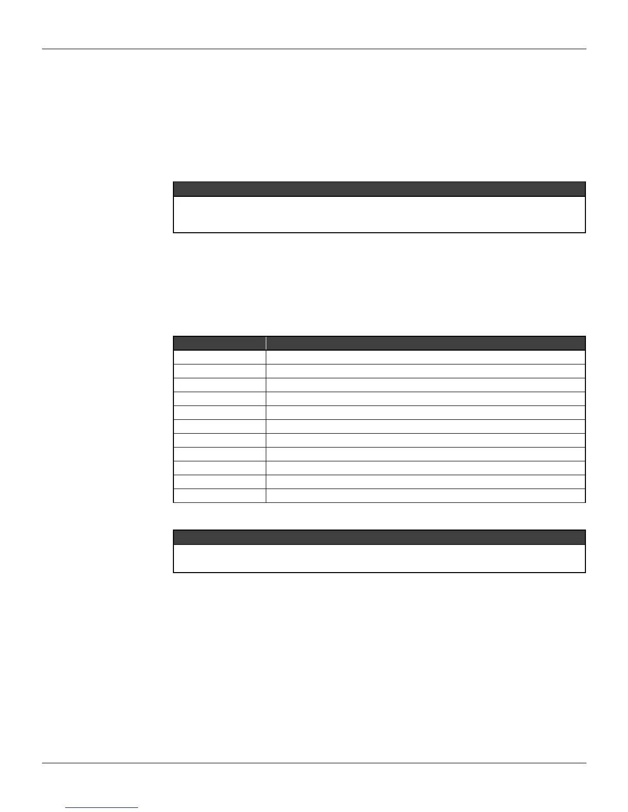
The LD301 may work with up to two display configurations to be alternately displayed at 3 second
intervals. Parameters that may be selected for visualization are those listed on Table 3.4, below.
PARAMETER DESCRIPTION
CURRENT
Current in mille amperes.
PV%
Process Variable in percentage.
PV
Process Variable in engineering units.
MV%
(*)
Output in percentage.
PR
Pressure in pressure unit.
TEMP
Ambient temperature.
TOTAL
Total accumulated by the totalizer.
SP%
(*)
Setpoint in percentage.
SP
(*)
Setpoint in engineering units.
ER%
(*)
Error in percentage (PV% - SP %).
NONE
Used to cancel the second indication.
Table 3.4 – Variables for Display Indication
NOTE
Items marked with an asterisk can only be selected in the PID mode.
Total can only be selected if enabled.
WRITING PROTECTION - This feature is used to protect the transmitter configuration from changes
via communication. All configuration data are writing-protected.
The LD301 includes two write protection mechanisms: software and hardware locking; software
locking has higher priority.
When the LD301 writing software protection mechanism is enabled, it is possible, by means of
specific commands, to enable or disable the write protection.
PASSWORDS - this service enables the user to modify the operation passwords used in the LD301.
Each password defines the access for a priority level (1 to 3); such configuration is stored in the
LD301 EEPROM. Password Level 3 is hierarchically superior to password level 2, which is superior
to level 1. The levels 1 and 2 are available for external access allowing configurator to create its
proper access structure.