Section 5
5.1
MAINTENANCE
General
NOTE
Equipments installed in hazardous atmospheres must be inspected in compliance with the IEC60079-
17 standard.
Below, there are some important maintenance procedures that should be followed in order to have safer
plant and easy maintenance.
In general, it is recommended that end users do not try to repair printed circuit boards. Spare circuit
boards may be ordered from SMAR whenever necessary.
The sensor has been designed to operate for many years without malfunctions. Should the process
application require periodic cleaning of the transmitter, the flanges may be easily removed and
reinstalled.
Should the sensor eventually require maintenance, it may not be changed on the field. In this case, the
possibly damaged sensor should be returned to SMAR for evaluation and, if necessary, repair. Refer to
the "Returning Materials" item at the end of this Section.
Diagnostic using Configuration Tool
Should any problem be noticed regarding the transmitter output, the configurator can be used to verify
what is the problem (see Table 5.1).
The configurator should be connected to the transmitter according to the wiring diagram shown on
Section 1, Figures 1.7, 1.8 and 1.9.
Error Messages
When communicating using the CONFIGURATOR the user will be informed about any problem found by
the transmitter self-diagnostics.
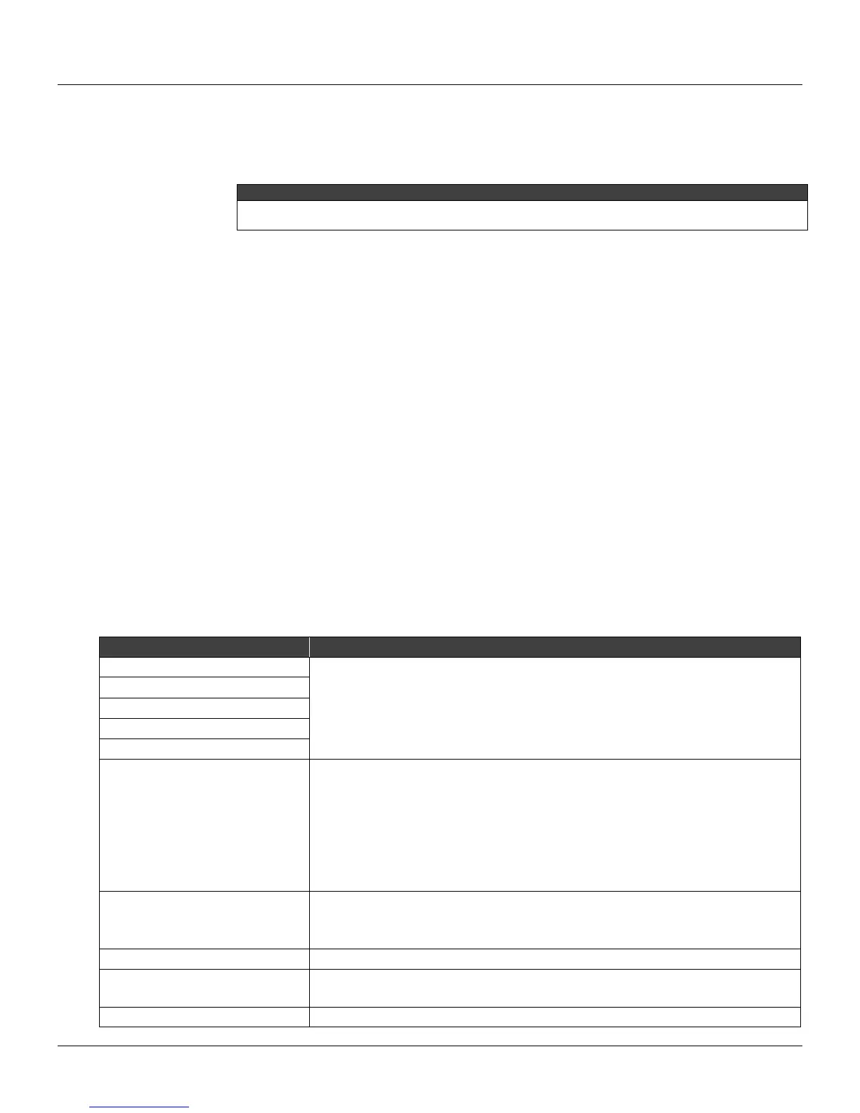
Table 5.1 presents a list of error messages with details for corrective actions that may be necessary.
ERROR MESSAGES POTENTIAL SOURCE OF PROBLEM
UART RECEIVER FAILURE:
The line resistance is not according to load limitation.
Excessive noise or ripple in the line.
Low level signal.
Interface damaged.
Power supply with inadequate voltage.
PARITY ERROR
OVERRUN ERROR
ERROR CHECK SUM
FRAMING ERROR
CONFIGURATOR RECEIVES NO
ANSWER FROM TRANSMITTER
Transmitter line resistance is not according to load limitation.
Transmitter not powered.
Interface not connected or damaged.
Repeated bus address.
Transmitter polarity is reversed.
Interface damaged.
Power supply with inadequate voltage.
CMD NOT IMPLEMENTED
Software version not compatible between configurator and transmitter.
Configurator is trying to carry out a LD301 specific command in a transmitter from
another manufacturer.
TRANSMITTER BUSY
Transmitter carrying out an important task, e.g., local adjustment.
XMTR MALFUNCTION
Sensor disconnected.
Sensor failure.
COLD START
Start-up or Reset due to power supplies failure.