LD301 – Operation and Maintenance Instruction Manual
6.6
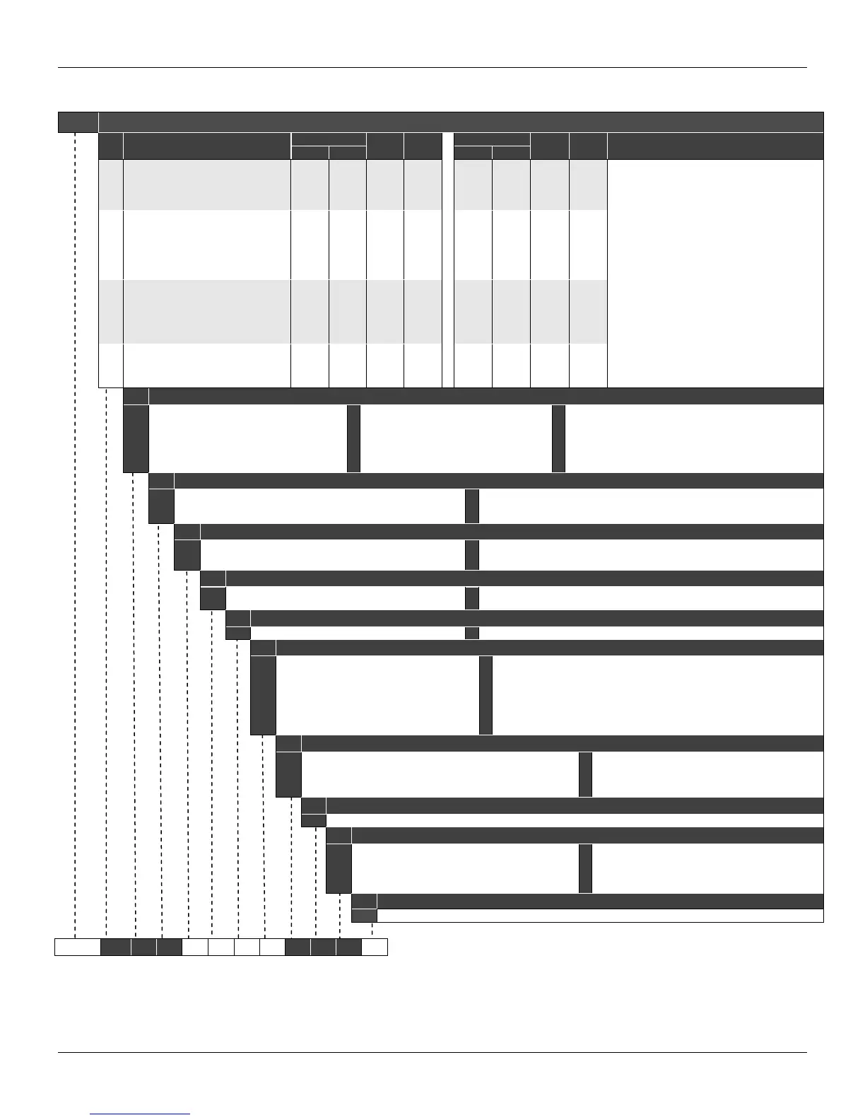
Ordering Code
MODEL DIFFERENTIAL , FLOW, GAGE, ABSOLUTE AND HIGH STATIC PRESSURE TRANSMITTER
COD.
Type
Range Limits
Min.
Span
Unit
Range Limits
Min.
Span
Unit
Min. Max. Min. Max.
D0
D1
D2
D3
D4
Differential and Flow
Differential and Flow
Differential and Flow
Differential and Flow
Differential and Flow
-1
-5
-50
-250
-2500
1
5
50
250
2500
0.05
0.13
0.42
2.08
20.83
kPa
kPa
kPa
kPa
kPa
-4
-20
-200
-14,7
-14,7
4
20
200
36
360
0,05
0,13
0,42
2,08
20,83
inH
2
O
inH
2
O
inH
2
O
psi
psi
NOTE: The range can be extended up to 0.75 LRL* and
1.2 URL** with small degradation of accuracy.
*LRL = Lower Range Limit.
**URL = Upper Range Limit.
M0
M1
M2
M3
M4
M5
M6
Gage
Gage
Gage
Gage
Gage
Gage
Gage
-1
- 5
- 50
-100
-100
- 0.1
- 0.1
1
5
50
250
2500
25
40
0.05
0.13
0.42
2.08
20.83
0.21
0.33
kPa
kPa
kPa
kPa
kPa
MPa
MPa
-4
-20
-200
-14,7
-14,7
-14,7
-14,7
4
20
200
36
360
3600
5800
0,05
0,13
0,42
2,08
20,83
0,21
0,33
inH
2
O
inH
2
O
inH
2
O
psi
psi
psi
psi
A1
A2
A3
A4
A5
A6
Absolute
Absolute
Absolute
Absolute
Absolute
Absolute
0
0
0
0
0
0
5
50
250
2500
25
40
2.00
2.50
5.00
20.83
0.21
0.33
kPa
kPa
kPa
kPa
Mpa
MPa
0
0
0
0
0
0
20
200
36
360
3600
5800
2,00
2,50
5,00
20,83
0,21
0,33
inH
2
O
inH
2
O
psi
psi
psi
psi
H2
H3
H4
H5
Differential – High Static Pressure
Differential – High Static Pressure
Differential – High Static Pressure
Differential – High Static Pressure
-50
-250
-2500
-25
50
250
2500
25
0.42
2.08
20.83
0.21
kPa
kPa
kPa
MPa
-200
-14,7
-14,7
-14,7
200
36
360
3600
0,42
2,08
20,83
0,21
inH
2
O
psi
psi
psi
COD.
Diaphragm Material and Fill Fluid
1
2
3
4
5
7
316 SST
316 SST
Hastelloy C276
Hastelloy C276
Monel 400
Tantalum
Silicone Oil (9)
Inert Oil Fluorolube (2) (15)
Silicone Oil (1) (9)
Inert Oil Fluorolube (1) (2) (15)
Silicone Oil (1) (3) (9)
Silicone Oil (3) (9)
8
9
A
D
E
G
Tantalum
316L SST
Monel 400
316L SST
Hastelloy C276
Tantalum
Inert Oil Fluorolube (2) (3) (15)
Fomblim Oil
Fomblim Oil (1) (3)
Inert Oil Krytox (3) (15)
Inert Oil Krytox (1) (3) (15)
Inert Oil Krytox (3) (15)
K
M
P
Q
R
S
Monel 400
Monel 400 Gold Plated
Monel 400 Gold Plated
316 SST
Hastelloy C276
Tantalum
Inert Oil Krytox (1) (3) (15)
Silicone Oil (1) (3) (9)
Inert Oil Krytox (1) (3) (15)
Inert Oil Halocarbon 4.2 (2) (3) (15)
Inert Oil Halocarbon 4.2 (2) (3) (15)
Inert Oil Halocarbon 4.2 (2) (3) (15)
COD.
Flange(s), Adapter(s) and Drain/Vent Valves Material
C
H
I
Plated CS (Drain/Vent in Stainless Steel) (16)
Hastelloy C276 (CW-12MW, ASTM-A494) (1)
316 SST – CF8M (ASTM A351)
M
N
P
Monel 400 (1)
316 SST – CF8M (ASTM A351) (Drain/Vent in Hastelloy C276) (1)
316 SST – CF8M (ASTM A351) Flange with PVDF (Kynar) Insert (4) (5) (7) (11)
COD.
Wetted O-Rings Materials
0
B
E
Without O’Rings
Buna N
Ethylene – Propylene (12)
T
V
Kalrez (3)
Teflon
Viton
Note: O-Rings are not available on the sides with remote Seals.
COD.
Drain/Vent Position
O
A
Without Drain/Vent
Drain/Vent (Opposite to Process Connection)
D
U
Bottom
Top
Note: For better drain/vent operation, vent valves are strongly recommended.
Drain/Vent valve are not available on the sides with remote seals
COD.
Local Indicator
0
Without Indicator 1 With Digital Indicator
COD.
Process Connections
0
1
3
5
9
T
V
1/4 - 18 NPT (Without Adapter)
1/2 - 14 NPT With Adapter)
Remote Seal (With Plug) (3) (8)
1/2 - 14 NPT Axial with PVDF Insert (5) (7) (14)
Remote Seal (Low Volume Flange (3) (4) (8)
1/2 - 14 BSP (With Adapter)
Manifold Valve Integrated to the Transmitter
B
D
F
H
Q
Z
High Side : 1/2 - 14 NPT and Low Side : Remote Seal (With Plug) (10) (12)
High Side : Remote Seal (With Plug) and Low Side – 1/2 - 14 NPT (10) (12)
High Side : 1/2 - 14 NPT and Low Side - Remote Seal (Low Volume Flange) (10) (12)
High Side : Remote Seal (Low Volume Flange) and Low Side -1/2 – 14 NPT (10) (12)
8mm hole without thread. According to DIN 19213 (13)
User’s specification
COD.
Electrical Connections
0
1
2
3
1/2
- 14 NPT (17)
3/4
- 14 NPT with 316 SST adapter for 1/2 - 14 NPT) (18)
3/4
- 14 BSP with 316 SST adapter for 1/2 - 14 NPT) (6)
1/2
- 14 BSP with 316 SST adapter for 1/2 - 14 NPT) (6)
A
B
Z
M20 X 1.5 (19)
PG 13.5 DIN (19)
User’s specification
COD.
Zero Span Adjustment
1 With Zero and Span Adjustment
COD.
Mounting Bracket for 2” Pipe or Surface Mounting
0
1
2
5
6
Without Bracket
Carbon steel bracket and accessories (16)
316 SST bracket and accessories
L type, carbon steel bracket and accessories (16)
L type, 316 SST bracket and accessories
7
9
A
Z
Carbon steel bracket. Accessories: 316 SST (16)
L Type, carbon steel bracket. Accessories: 316 SST (16)
Flat, 304 SST bracket and 316 SST accessories
User’s specification
COD.
Continues next page
TYPICAL MODEL NUMBER
LD301 D2 1 I B U 1 0 0 1 2