11
EN
ATyS / ATySr - 541630C - SOCOMEC
1
2
2
1
3
125 A 160 A 200 A 250 A
3 P 4 P 3 P 4 P 3 P 4 P 3 P 4 P
in mm in mm in mm in mm in mm in mm in mm in mm
C
9.61 244 9.61 244 9.61 244 9.61 244 9.61 244 9.61 244 9.61 244 9.61 244
CA
0.39 10 0.39 10 0.39 10 0.39 10 0.39 10 0.39 10 0.59 15 0.59 15
F
11.28 286,5 12.48 317 11.28 286,5 12.48 317 11.28 286,5 12.48 317 12.91 328 14.88 378
M
4.72 120 5.91 150 4.72 120 5.91 150 4.72 120 5.91 150 6.30 160 8.27 210
T
1.42 36 1.42 36 1.42 36 1.42 36 1.42 36 1.42 36 1.97 50 1.97 50
U
0.79 20 0.79 20 0.79 20 0.79 20 0.79 20 0.79 20 0.98 25 0.98 25
W
0.35 9 0.35 9 0.35 9 0.35 9 0.35 9 0.35 9 0.43 11 0.43 11
X
1.10 28 0.87 22 1.10 28 0.87 22 1.10 28 0.87 22 1.30 33 1.30 33
315 A 400 A 500 A 630 A
3 P 4 P 3 P 4 P 3 P 4 P 3 P 4 P
in mm in mm in mm in mm in mm in mm in mm in mm
C
9.61 244 9.61 244 9.61 244 9.61 244 12.64 321 12.64 321 12.64 321 12.64 321
CA
0.59 15 0.59 15 0.59 15 0.59 15 0.59 15 0.59 15 0.79 20 0.79 20
F
12.91 328 14.88 378 12.91 328 14.88 378 14.84 377 17.20 437 14.84 377 17.20 437
M
6.30 160 8.27 210 6.30 160 8.27 210 8.27 210 10.63 270 8.27 210 10.63 270
T
1.97 50 1.97 50 1.97 50 1.97 50 2.56 65 2.56 65 2.56 65 2.56 65
U
1.38 35 1.38 35 1.38 35 1.38 35 1.26 32 1.26 32 1.77 45 1.77 45
W
0.43 11 0.43 11 0.43 11 0.43 11 0.55 14 0.55 14 0.51 13 0.51 13
X
1.30 33 1.30 33 1.30 33 1.30 33 1.67 42,5 1.48 37,5 1.67 42,5 1.48 37,5
W
U
CA
5.43
138
3.98
101
X T
Fix. M
F
C
Fix. 7.38
187,5
0.83
21
9.04
229,5
0.49
12,5
0.30
7,5
0.34
8,6
0.64
16,2
0.64
16,2
0.34
8,6
90°
90°
I II
0
3x
Ø 4-8 mm
1
2
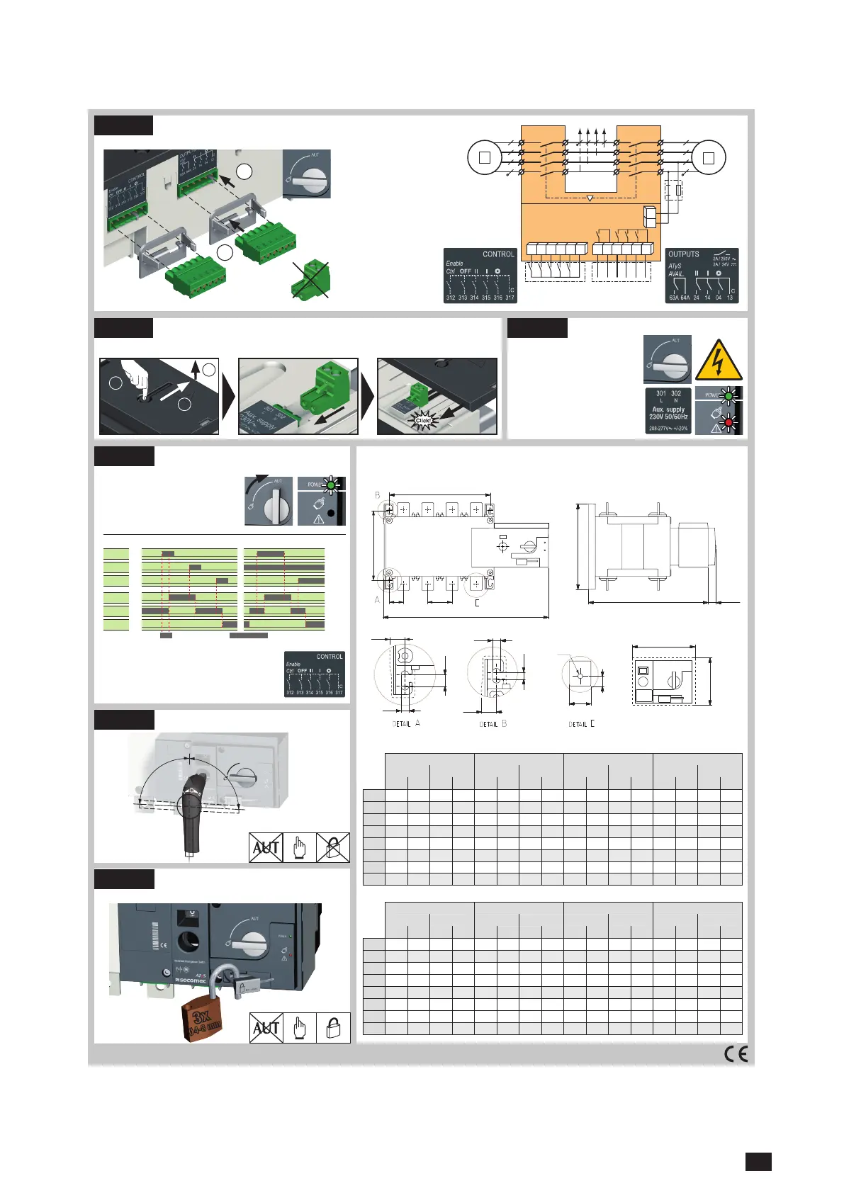
301 3022
312313 314315 316317 63A64A 24 14 04 13
CONTROL OUTPUTS
Imp. ≥60ms maintened
To enable control, close contact 312 with 317.
To force the product to 0 position/OFF bridge the contact
313 with 317. For contactor logic bridge contact 316
with 317. To operate: close the contact corresponding
to the desired position.
Connect the product with a cable of
section of 1,5 to 2,5 mm
2
.
Screw M3 - Tightening torque:
min.: 0.5 Nm - max.: 0.6 Nm
min.: 4.43 lbin - max.: 5.31 lbin
ATyS Voltage
Sensing and
Power supply
Kit excludes the
need for fuses
F1 & F2.
Ensure that the product is in Manual Mode.
CONTROL / COMMAND Terminals
STEP 3
STEP 5
Check
Whilst in manual mode, check
the wiring and if ok power up the
product.
LED “Power” Green: ON
LED Manuel/Defaut Red
(Productnot Available): ON
Power Supply Terminal
Remove the Top cover to access and connect the terminal - Replace the cover before putting in service.
STEP 4
Dimensions in./mm.
STEP 6A
Automatic Operation
Ensure that the emergency handle is not
inserted in the product and turn the mode
selector to the AUT position.
LED “Power” Green: ON
LED Manuel/Default: OFF
Manual Operation
Padlocking Mode
(as standard : in position O)
STEP 6C
STEP 6B
Non contractual document.
Subject to change without notice.CORPORATE HQ CONTACT: SOCOMEC SAS 1-4 RUE DE WESTHOUSE - 67235 BENFELD, FRANCE - WWW.SOCOMEC.COM
Contactor logicImpulse logic
order I
position I
order 0
position 0
order II
position II
 Loading...


