Chapter 9 - Tips and tricks for cable testing
Copyright 2016 Softing Industrial Automation GmbH
45
The BC-700-PB uses amongst other methods impulse reflectometry for assessing the cabling and
classifying and locating errors on the cable. Multiple cable errors, which exist simultaneously on the
cable may result in an imprecise cable test result. The more the corrective repair of the cable is
proceeding, the more precise the cable test results in the corresponding PROFIBUS cable segment will
be.
Electromagnetic interferences may influence PROFIBUS cable testing in a negative manner because
cable conductors may act like an antenna. Consider this aspect during cable testing and take care of
proper functional earthing of your plant respectively. Existing high frequency noise voltage may
negatively influence the BC-700-PB if operated by means of the external power supply. We recommend
operating on the BC-700-PB by means of the built-in battery under the above mentioned prevailing
conditions.
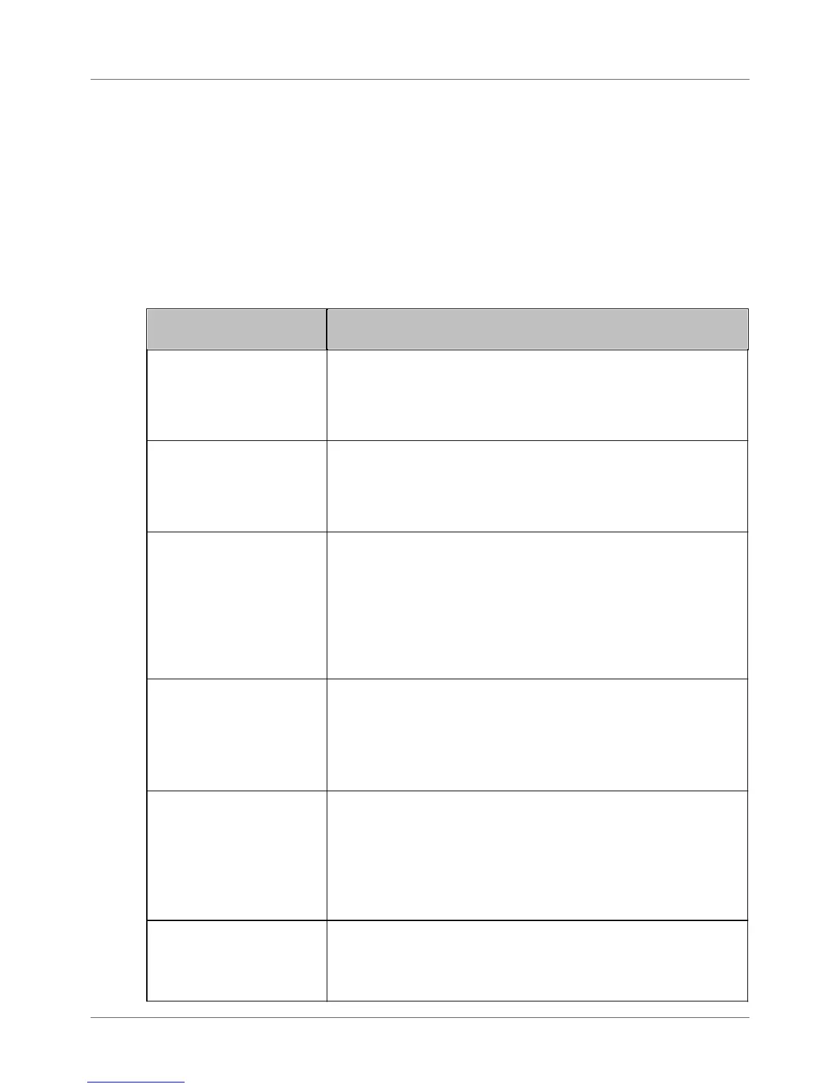
Cable testing error message
displayed on BC-700-PB
Remedial measures - starting points for correctly interpreting and
repairing the indicated fault
The green signal line of the PROFIBUS-cable is broken. Search for
damage on the cable in the vicinity of the indicated error location.
Fatigue breakage or a faultily assembled PROFIBUS-connector may
cause this error. The green signal line typically is connected to Pin 8 of
the PROFIBUS Sub-D type connector.
The red signal line of the PROFIBUS-cable is broken. Search for damage
on the cable in the vicinity of the indicated error location. Fatigue
breakage or a faultily assembled PROFIBUS-connector may cause this
error. The red signal line typically is connected to Pin 3 of the
PROFIBUS Sub-D type connector.
The shielding conductor is broken in the tested cable segment.
Alternatively electromagnetic shielding is not applied for in a
continuous manner. Search for damage on the cable in the vicinity of
the indicated error location. Fatigue breakage or a faultily assembled
PROFIBUS-connector may cause this error.
In rare cases electromagnetic shielding may be disrupted intentionally
in order to avoid electromagnetic interferences. Check this issue with
the planning personnel of the PROFIBUS-facility.
Short circuit between A and B
There is an unusual low ohmic or capacitive resistance between signal
lines A and B. Search for damage on the cable in the vicinity of the
indicated error location. A severe crush of the cable or multiple
unpowered bus terminators may cause this error.
In addition search for illegal spur lines and check, if moisture
penetrated the cabling or if the cabling is heavily soiled.
Short circuit between A and
shield
Short circuit between B and
shield
Short circuit between A, B
and shield
There is an unusual low ohmic or capacitive resistance between the
mentioned signal lines and conductors. Search for damage on the cable
in the vicinity of the indicated error location. A severe crush of the
cable or a faultily assembled PROFIBUS-connector may cause this
error.
In addition search for illegal spur lines and check, if moisture
penetrated the cabling or if the cabling is heavily soiled.
Capacitive Load / Spur Line
There is an unusual capacitive load between signal lines A and B and
the shield conductor. An illegal spur line or interference-suppression
capacitors may cause this error. This is common usage with "over-
compensated" or defective PROFIBUS-devices.