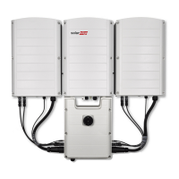
Figure 23: Connecting the Connection Unit to the Secondary Unit
d.
Assemblethetwopartsofthecablelock(suppliedwiththeinverter)aroundthecable
connector,makingsurethattheorientationoftheprintedtextonthelockiscorrect.
Pushthepartstogetheruntiltheyclicktolock.Toopenthelockuseaflat-bladed
screwdriver.
Figure 24: Cable lock
l
DCcablestoDC+andDC-connectors:
ConnecttheDCwiresandtheDCinterlocktrimmerlinesfromtheSecondaryUnit(s)tothe
ConnectionUnit,usingthesuppliedconduits.TheDCwiresandtheinterlocklinesarepre-
connectedtotheSecondaryUnit.Theinverterinterlockisusedtomechanicallyinterlockthe
inverterunitstotheConnectionUnit.Thisallowsremovaloftheunitswithoutriskof
electricalhazards.
a. FeedthetwointerlocktrimmerlinestogetherwiththeDCcablesthroughtheconduit
suppliedwiththeinverter.
b.
AttachtheconduitconnectortotheconduitentryatthebottomoftheSecondaryUnit
andpushitinuntilitclicksintoplace.
Figure 25: Connecting the conduit to the Secondary Unit
c. FeedthetwointerlockcablestogetherwiththeDCcablesthroughtheconduitentryat
thesideoftheConnectionUnit.
-Three Phase Inverter with Synergy Technology Installation MAN-01-00402-1.4
34
Mounting and Connecting the Primary and Secondary Unit(s)

 Loading...