InvertersmayhaveadifferentnumberofpairsofDCinputterminals,dependingontheinverterpower
rating.Ifmorestringsarerequired,theycanbeconnectedinparallelusinganexternalcombinerbox
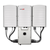
beforeconnectingtotheConnectionUnit;stringsconnectedtodifferentunitscannotbecombined.
Whenconnectingmultiplestrings,itisrecommendedtorunseparatecircuitstotheConnectionUnitor
topositionthecombinerboxneartheConnectionUnit.Thissimplifiescommissioningbyallowingtesting
andservicingneartheinverter.
To connect the strings to the Connection Unit with glands/Conduits:
1. Strip5⁄16''(8mm)oftheDCwireinsulation.
2. InserttheDCconduitintotheDC-sideopeningontheConnectionUnit(leftsideatthebottomofthe
ConnectionUnit).
3. Equipmentgrounding:ConnecttheDCequipmentgroundconductortotheequipmentgrounding
terminalblock(bus-bar)intheConnectionUnit.
NOTE
Functional Electrical Earthing of DC-side negative or positive is prohibited because the inverter has no
transformer. Equipment grounding of exposed conductive surfaces in the array is required per the NEC.
4.
ConnecttheDCwirestotheDC+andDC-terminalblocks,accordingtothelabelsontheterminals.
or;connecttwowires(DC+andDC-)perstring:
a. Useastandardflat-bladescrewdrivertoconnectthewirestothespring-clampterminals.The
screwdriverbladeshouldfitfreelyintheterminalopening.Toolargeabladecancracktheplastic
housing.
b. Insertthescrewdriverandfirmlytiltittopressthereleasemechanismandopentheclamp.
c. Insertthewireintothetopopening(seeFigure31).
d. Removethescrewdriver–thewireisautomaticallyclamped.
CAUTION!
Ensure that the Plus (+) wire is connected to the + terminal and that the Minus (-) wire is connected to
the Minus (-) terminal connector.
Veillez à ce que le câble Plus (+) soit connecté au terminal + et que le câble - soit connecté au
connecteur terminal.
NOTE
For systems with four PV strings per unit or more, fuses may need to be installed in
both the positive and negative conductors as required by NEC Article 690.9. For more
information, refer to the Technical Note “String Fusing Requirements in SolarEdge
Systems” at http://www.solaredge.com/files/pdfs/string_fusing_requirements.pdf.
Figure 31: DC Spring-clamp terminals
-Three Phase Inverter with Synergy Technology Installation MAN-01-00402-1.4
40
Connecting the Strings to the Connection Unit