59
Electrical Connection
+
-
+
-
Meter/CT
Parallel 1Parallel 2 Parallel 1Parallel 2
CAN
Inverter
Master
Inverter
Slave
PV+ PV- Battery
PV+ PV- Battery
PE PE PE
PE
Meter
R RS T N S T N
Grid EPS
Grid EPS
R
S
T
N
Three-phase
Normal Load
Three-phase
Normal Load
Single-phase
Normal Load
Single-phase
Normal Load
Single-phase
Normal Load
R
S
T
N
NLR S T N
NL
NL
RSTN
Grid
R S T N
R S T N
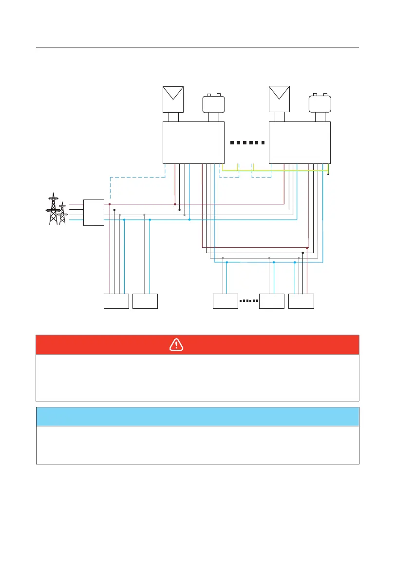
Figure 7-32 System diagram without SolaX X3-PBOX-150kW-G2
WARNING!
• The parallel system is extremely complex and a large amount cables need to be
connected, therefore it is strongly required that every cable must be connected
according to correct line sequence (R-R, S-S, T-T, N-N), otherwise any small
misoperation may cause the system running failed.
NOTICE!
• Please refer to
X3-PBOX-150kW-G2 Installation Guide
for parallel connenction on
X3-PBOX-150kW-G2 side.
• Please refer to "9.6 Parallel Status" for the corresponding setup on the inverter.

 Loading...