CChhaannnneell SSttrriipp
IInnttrroodduuccttiioonn
Duality SE’s Split Mode enables the channel processing to be easily applied to
channel input signals feeding the DAW record path or to the DAW returns. This
provides the equivalent of in-line operation but without the complexity of separate
channel and monitor paths.
Users who are familiar with SSL’s range of in-line consoles will soon realise that the
channel strip faders can control virtual faders on the workstation as well as the
channel signal path, in many ways paralleling the large/small fader configuration of
an in-line channel strip. This provides an alternative to Split Mode working, with the
DAW console handling the functions of a monitor mixer.
The channel supports two input connections, the Monitor Input which is
normally sourced from the output of the DAW, and the Channel input which
accepts variable level signals from a microphone, DI box or other audio source.
Three preamps are available for use with either input: a unity gain line level buffer
which is normally assigned to the DAW return, and a pair of mic preamps sourced
from the CHANNEL input XLR connector, one using SSL’s Super Analogue direct
coupled DC servo circuitry, and the other featuring SSL’s proprietary VHD™
(Variable Harmonic Drive) valve emulation gain stage. The channel output can route
to 24 Track Busses, any one of three stereo Main Mix Busses (A, B and C) or all
the Main Mix Busses in 5.1 mode.
In addition to two Cue Stereo sends and four mono FX Sends, a dedicated Direct
Output (CH OP) is provided. Each channel has comprehensive routing for EQ and
filter, dynamics, and insert send/return points.
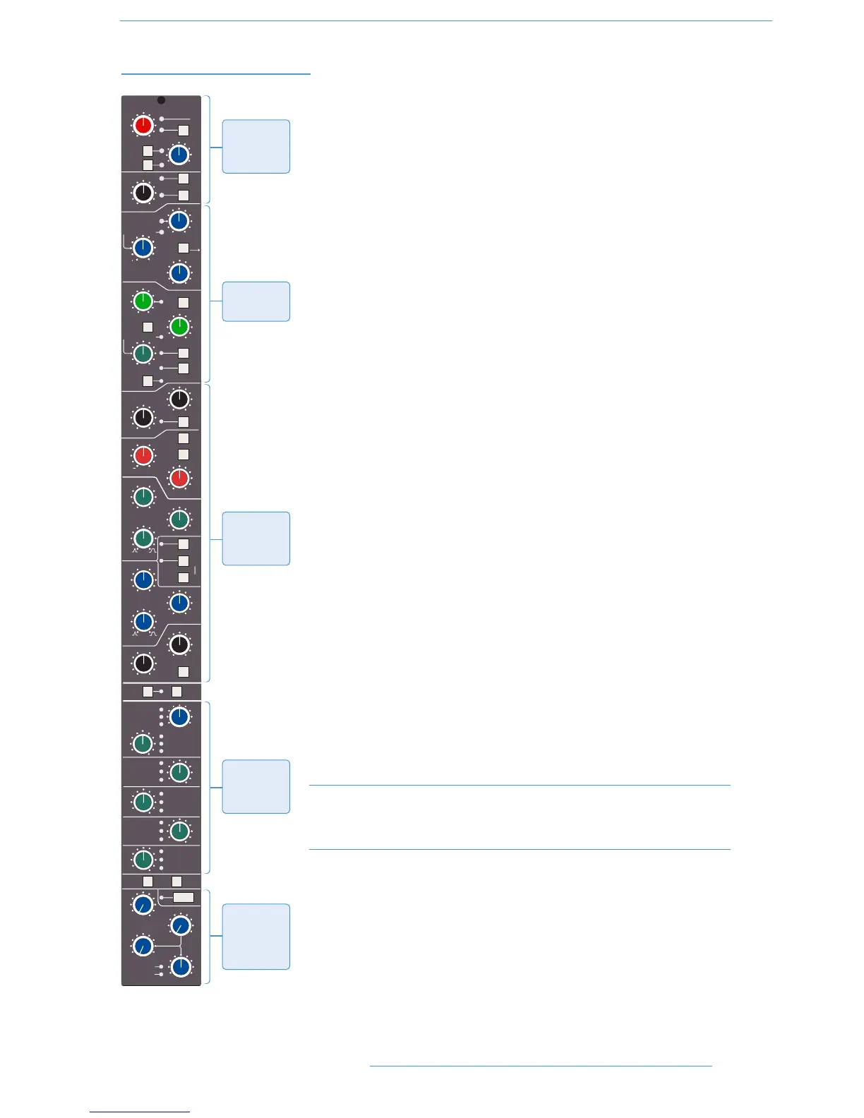
The channel strip can be divided into five distinct functional sections (See left):
1. Channel input
2. Dynamics
3. EQ and filter
4. Cue Stereo and FX outputs
5. Channel output pan
Note that a number of channel parameters are adjusted via the Central Routing
Panel in the Centre Section, described later in this section. This panel is assigned
to a channel by pressing the Select button at the base of the channel’s fader.
Beneath the channel strips is a panel containing the ‘D-pot’ for DAW output or
channel level control. This area also houses cut and solo buttons for both fader and
D-pot, and an electronic scribble strip. Finally, below the electronic scribble strip,
each channel has a long-throw (100mm) moving fader.