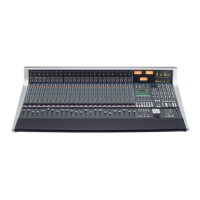
FFiilltteerrss
These comprise a 3rd Order 18dB/Octave high pass filter (HF) and a 2nd Order
12dB/Octave low pass filter (LF). Each filter is out of circuit when the control is fully
anticlockwise. When the filter is in circuit, the FILTER box on the channel TFT display is
highlighted.
Normally, the filters follow the EQ section in the signal chain but the FILT to INP button in the input section of
the channel strip places the filters directly after the channel input. This function is also available on the central
routing panel. Pressing TO S/ch routes the filter section to the dynamics sidechain.
Signal processing order is graphically displayed on the channel TFT screen
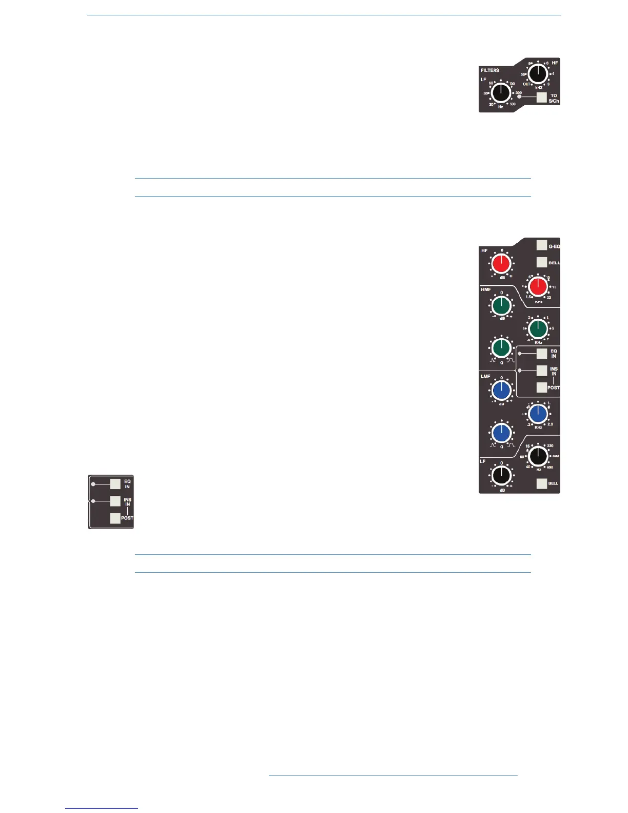
EEqquuaalliisseerr
This is a four band parametric equaliser based on SSL’s classic 'Black Knob' EQ, which was
developed for the original SL4000E series console. Selecting the G-EQ button introduces
steeper shelving curves with a controlled amount of undershoot at the turnover frequency,
together with the classic gain/bandwidth interaction for the mid band sections that was a key
characteristic of the original G-Series EQ.
The individual bands function as follows: HF high frequency shelving equaliser switchable to
fixed Q parametric (BELL); HMF high frequency parametric mid band equaliser; LMF low
frequency parametric mid band equaliser; LF low frequency shelving equaliser switchable to
fixed Q parametric (BELL). The EQ IN button (located next to the insert buttons) routes
the channel signal through the EQ and filter section. When in circuit, the EQ box on the
channel TFT display is highlighted. See also Central Routing Control.
IInnsseerrtt
The INS IN button routes the channel signal via balanced insert send and return points,
available on the rear of the console (D-connectors). The insert defaults to the channel input
(post the input trim); POST cycles the insert position through two alternative
locations in the processing path: post EQ or post Dynamics; the centre section
master routing panel provides individual INS POST EQ and INS POST
DYN buttons. When the insert is active, the INSERT box on the channel
TFT is highlighted.
Signal processing order is graphically displayed on the channel TFT screen
22--77
CCoonnssoollee OOppeerraattiioonnss
DDuuaalliittyy SSEE OOppeerraattoorr’’ss MMaannuuaall