DD--ppoott aanndd DDAAWW CCoonnttrrooll
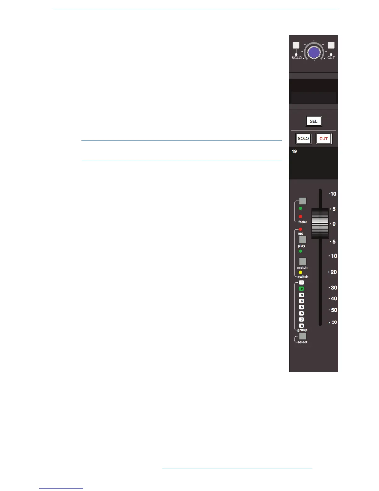
Below the channel strips is a 8-wide panel containing a rotary encoder known as the D-pot,
together with its integral momentary switch mounted on the encoder shaft. This is used to
adjust the currently assigned DAW parameter or the analogue channel level; D-pot functions
are assigned from the centre section, and indicated in the D-pot’s associated two line display.
The CUT and SOLO buttons above the encoder are used when the encoder is controlling
the DAW or Duality SE channel gain.
The electronic scribble strip displays the channel name, the name of a DAW track, selected
DAW send, or I/O data according to the function currently assigned on the Master Control
Panel (see Section 3). When the rotary control and the fader swap roles for gain control,
entries in the scribble strip also flip.
Note that on consoles manufactured before October 2009, the electronic scribble strip
and the controls immediately above it are slightly different in appearance.
The SEL button operates the DAW ‘Selected Channel’ function. This function can be re-
assigned from the centre section, to track arm a selected DAW channel or assign the ‘plug-in’
editor (Pro Tools only). Tallies in the channel meter display Record Ready and Edit status
regardless of whether the console is in ‘DAW Focus Mode’ (see Section 3 for more details).
CChhaannnneell CCuutt aanndd SSoolloo
The CUT and SOLO buttons above the traditional scribble strip function in the normal
way, providing muting and solo auditioning of channels.
CChhaannnneell FFaaddeerr
The 100mm moving fader controls the analogue channel, or assigned DAW track, or the
DAW send level when the centre section ‘flip’ function is active (Pro Tools/HUI and MCU
interfaced DAWs), plus Plug-In parameters when using a MCU compatible DAW. The required
function is selected via the Master Control Panel (see Section 3 for details).
The fader button, and associated LEDs are used in conjunction with the DAW automation
(HUI interface only) or the optional Duality SE automation and ‘multi-operator’ Total Recall
systems. The play and match buttons are used only with Duality SE automation. See
Sections 4 and 5 for more details.
The select button at the foot of the fader is used to select that channel to the central
routing panel, and for fader grouping (see below).
F
F
a
a
d
d
r
r
2
2
5
5
22--1111
CCoonnssoollee OOppeerraattiioonnss
DDuuaalliittyy SSEE OOppeerraattoorr’’ss MMaannuuaall