Levelogger Series User Guide
Page 28
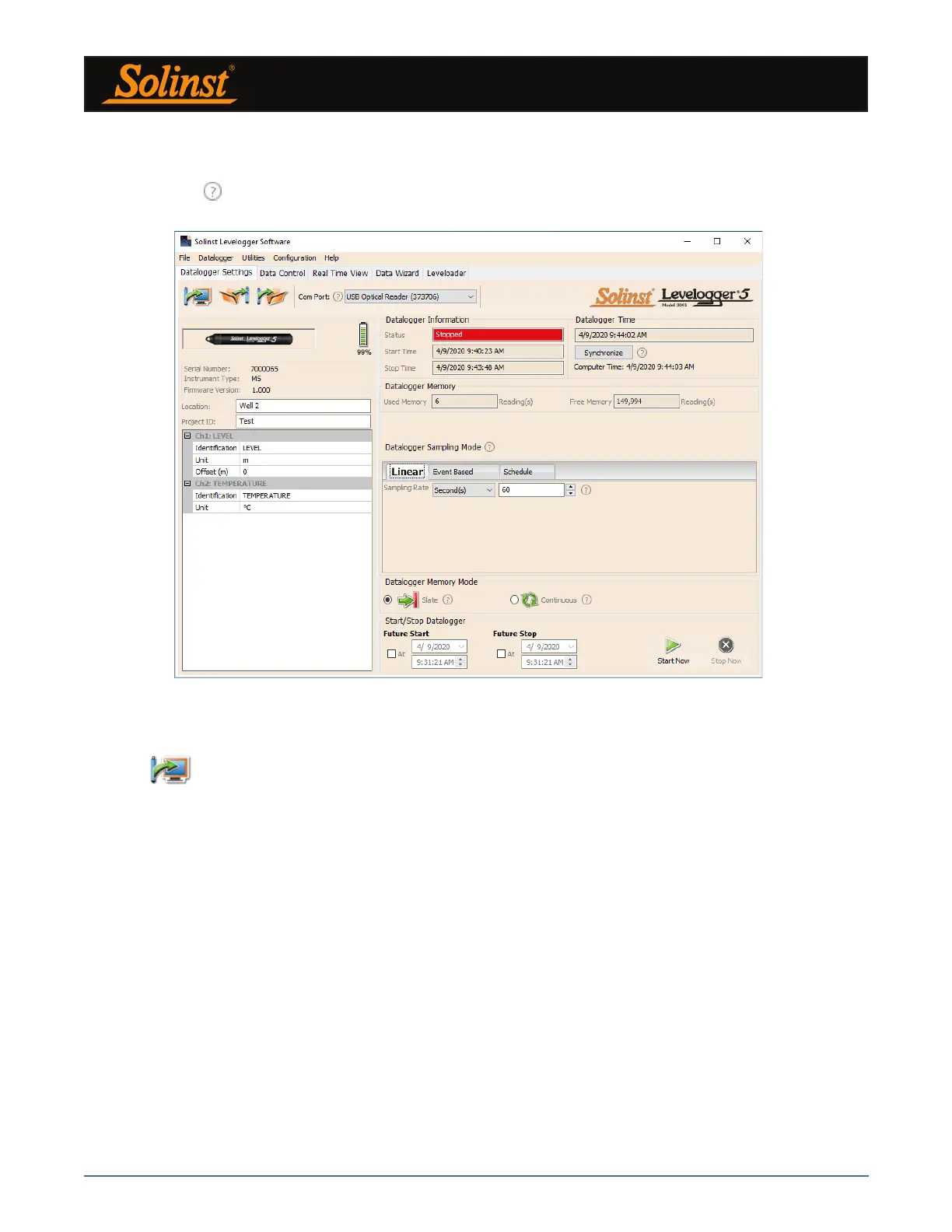
Figure 5-1 Datalogger Settings Tab
Select the appropriate Com Port for the connected communications device from the centre drop-down menu.
Click
to retrieve the current settings from the connected datalogger.
5.1 Datalogger Settings
After you have retrieved the settings of the connected datalogger, the Datalogger Settings tab will identify
the Instrument Type, Serial Number, Firmware Version, Project ID, Location, Battery Level and the Channel
Settings.
• Instrument Type: will display the model of the attached datalogger, i.e.: M30, Barologger,
Rainlogger.
• Serial Number: the unique serial number of the attached datalogger will be displayed.
• Firmware Version: shows the firmware version of the attached datalogger.
• Project ID: input your own identification system. The Project ID is limited to 32 characters.
• Location: input specific site / location information. The location is limited to 32 characters.
Note: When first setting up a Barologger and Levelogger(s) that will be used for the same project, it is suggested
to set them at the same sampling interval, and to use the Future Start and Stop options where possible. When the
data sets have the same time stamps, and start and stop times, barometric compensation of the data will be most
accurate. It is also useful to synchronize the clocks of the dataloggers. See Section 5.4.
After you start the Levelogger Software, the main Levelogger Software window will appear, with the
Datalogger Settings tab open.
Note: Click on icons to get an explanation of that software feature.