Levelogger Series User Guide
Page 66
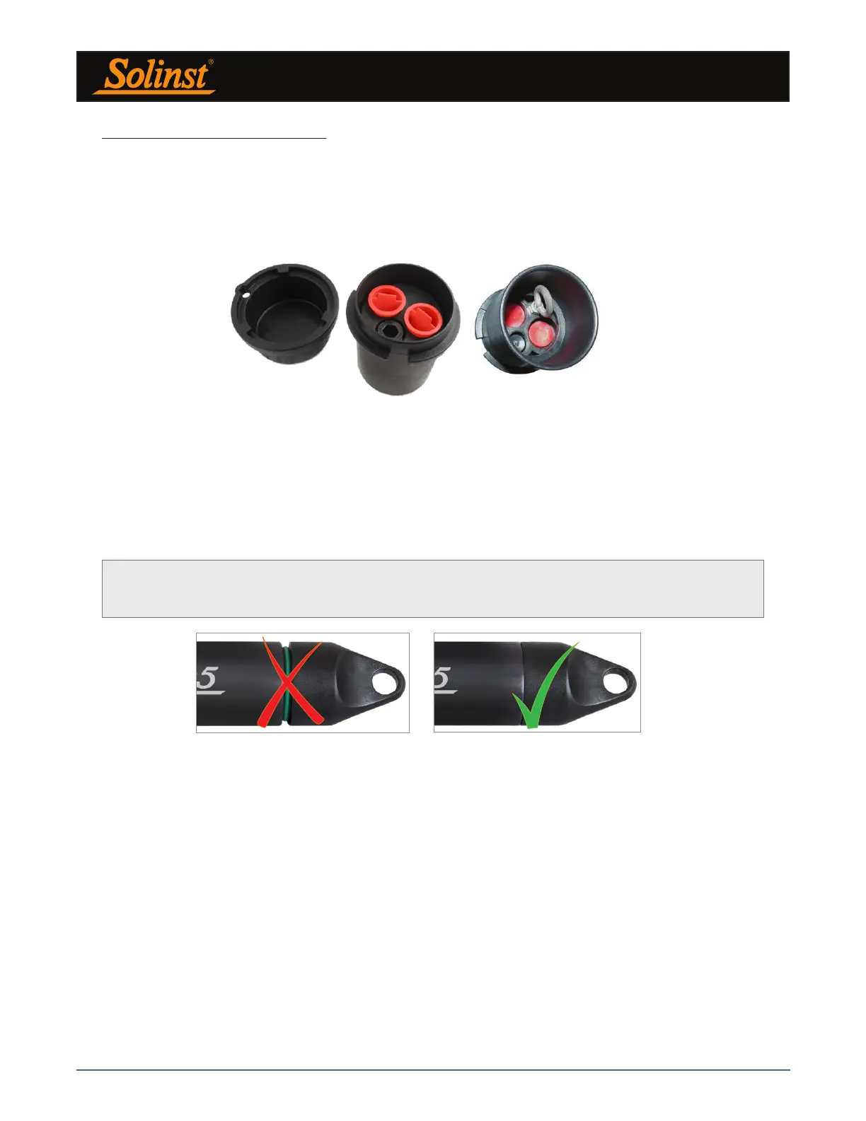
Before deployment, to ensure a water-tight seal, tighten the installation cap onto the Levelogger until
there is no green o-ring visible.
10.1.1 Free Suspended Installations
10.1.1.1 Suspension Wire/Cord Installation
When installing on a suspension wire or cord, the Levelogger is pre-programmed and started using the software.
It is then deployed with the suspension wire or cord connected to the installation cap of the Levelogger to the
underside of a well cap.
Figure 10-2 Solinst 2" Locking Well Cap for Wireline or Kevlar Cord
Note: The o-ring on the optical end of the Levelogger should be inspected regularly and replaced as
required. See Section 10.2.
Solinst supplies stainless steel suspension wire assemblies including SS stranded wire and hooks available
in a variety of lengths from 15 m (50 ft) to 150 m (500 ft), and Kevlar cord assemblies to 150 m (500 ft).
Solinst also supplies the Model 3001 2" Well Cap Assembly from which the Levelogger can be suspended.
An Adaptor for 4" wells is also available (see Section 10.1.1.3).
The data is retrieved manually, by withdrawing the Levelogger, removing the installation cap and attaching a
Field Reader 5 or Desktop Reader 5 (see Section 2). This type of installation is applicable to both submerged
and barometric applications.
Note: There is also the option to communicate with a DataGrabber 5 or Levelogger 5 App Interface (see separate
User Guides).
Figure 10-3 Proper Installation Cap Connection