ix
I-V CURVE TERMINOLOGY .................................................................................................................................... 7-2
Performance Factor ........................................................................................................................................... 7-2
Fill Factor .......................................................................................................................................................... 7-2
THE SHAPE OF A NORMAL I-V CURVE ................................................................................................................... 7-3
INTERPRETING I-V CURVES ................................................................................................................................... 7-4
1. NOTCHES OR STEPS ............................................................................................................................................ 7-6
Array Is Partially Shaded, or non-uniform soiling or debris is present ............................................................. 7-8
PV Cells Are Damaged ..................................................................................................................................... 7-8
Cell String Conductor Is Short Circuited .......................................................................................................... 7-8
2. LOW CURRENT ................................................................................................................................................... 7-8
Uniform soiling ................................................................................................................................................. 7-9
Strip shade ........................................................................................................................................................ 7-9
Dirt dam ............................................................................................................................................................ 7-9
Module Degradation ....................................................................................................................................... 7-10
Incorrect PV Module Is Selected for the PV Model ....................................................................................... 7-10
Number of PV Strings in Parallel Is Not Entered Correctly in the Model ...................................................... 7-10
Irradiance Changed Between Irradiance and I-V Measurements .................................................................... 7-10
Irradiance Sensor Is Not Oriented in the Plane of Array ................................................................................ 7-10
Albedo Effects (reflection) Contribute Additional Irradiance ........................................................................ 7-10
Irradiance Is Too Low, or the Sun Is Too Close to the Horizon ..................................................................... 7-11
Manual Irradiance Sensor Is Not Accurate ..................................................................................................... 7-11
3. LOW VOLTAGE ................................................................................................................................................. 7-11
PV Cell Temperature Is Hotter than the Measured Temperature .................................................................... 7-12
One or More Cells or Modules Are Completely Shaded ................................................................................ 7-12
One or More Bypass Diodes Are Conducting or Shorted ............................................................................... 7-12
4. ROUNDER KNEE ................................................................................................................................................ 7-13
5. STEEPER SLOPE IN HORIZONTAL LEG ................................................................................................................ 7-14
Shunt Paths Exist in PV Cells or Modules ...................................................................................................... 7-14
Module I
sc
Mismatch ....................................................................................................................................... 7-15
Tapered shade or dirt dam ............................................................................................................................... 7-15
6. LESS STEEP SLOPE IN VERTICAL LEG ................................................................................................................. 7-16
PV Wiring Has Excess Resistance or Is Insufficiently Sized ......................................................................... 7-16
Electrical Interconnections in the Array Are Resistive ................................................................................... 7-17
Series Resistance of PV Modules Has Increased ............................................................................................ 7-17
TROUBLESHOOTING PV ARRAYS ......................................................................................................................... 7-17
8 TRANSLATION OF I-V DATA TO STANDARD TEST CONDITIONS ..................................................... 8-1
PARAMETER DEFINITIONS ...................................................................................................................................... 8-1
TRANSLATION EQUATIONS ..................................................................................................................................... 8-2
Figures
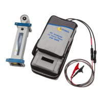
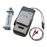
FIGURE 1. TEST LEADS AND CLIPS RATED FOR USE WITH THE PVA-1500S ............................................................... 1-18
FIGURE 2. WELCOME SCREEN ................................................................................................................................... 1-27
FIGURE 3. PREREQUISITES DIALOG ........................................................................................................................... 1-28
FIGURE 4. INSTALLATION DEFAULT LOCATION DIALOG ............................................................................................ 1-28
FIGURE 5. INSERT WIRELESS USB ADAPTER DIALOG ................................................................................................ 1-29
 Loading...