Do you have a question about the Solmetric PVA-1500T and is the answer not in the manual?
Grants a nonexclusive license to use PC and Embedded Software.
Allows making one copy of PC Software for backup or archival purposes.
Lists prohibited actions for software/documentation usage.
Details rights for transferring PC and Embedded Software.
Details warranty against defects in materials and workmanship for one year.
Outlines the exclusive remedy for warranty claims, typically repair or replacement.
Explains when the agreement takes effect and conditions for termination.
States that software contains trade secrets and proprietary know-how.
Lists Solmetric's trademarks and registered trademarks.
Outlines general terms and conditions of the license agreement.
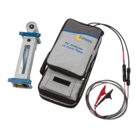
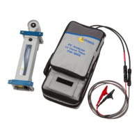
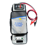
Introduces the PV Analyzer, its purpose, and components.
Lists the minimum hardware and OS requirements for using the software.
Details the Curve Tracer and SolSensor equipment included.
Provides detailed electrical and mechanical specifications for various models.
Covers safety information and regulatory compliance for the instruments.
Lists important precautions for using the instruments.
Details the steps for installing the I-V Measurement Unit and software.
Explains how to charge the batteries for the instruments.
Details the wireless network setup for communication.
Describes the system controls and operational states of the measurement units.
Provides instructions for setting up the I-V Measurement Unit.
Provides instructions for setting up the SolSensor.
Details how to mount the SolSensor onto a PV module frame.
Offers tips for improving wireless signal strength and range.
Explains how to mount the SolSensor using a tripod for optimal placement.
Guides on connecting the I-V Measurement Unit to PV equipment.
Instructions on how to power on the I-V Measurement Unit.
Explains how to perform I-V measurements using the unit.
Describes how to disable the I-V sweep sequence for safety.
Details over-voltage warnings and protection mechanisms.
Details over-current warnings and protection mechanisms.
Explains the reverse polarity protection feature.
Explains how to use the project feature for organizing measurements.
Describes the system tree for visualizing and managing array data.
Provides an overview of the main screen of the PV Analyzer software.
Details the functions available in the menu bar.
Explains how to use the different tabs for data viewing.
Explains the structure and content of exported I-V data files.
Describes the basis for PV performance predictions made by the software.
Explains how short-circuit current (Isc) is measured.
Instructions on how to update the PV Analyzer PC software.
Information on updating instrument firmware.
Details preparations before going to the field for measurements.
Outlines the process of making measurements in the field.
Guides on setting up the I-V Unit, SolSensor, and connecting the equipment.
Outlines the process of performing I-V measurements, inspecting results, and saving data.
Guides on troubleshooting using status messages displayed by the software.
Provides troubleshooting steps based on observed symptoms.
Introduces the importance of irradiance and temperature for array performance evaluation.
Details how to measure irradiance using the SolSensor.
Explains how to orient and mount the irradiance sensor for accurate readings.
Explains how to calculate irradiance from measured I-V curve data.
Describes how to manually enter irradiance values.
Details how to measure module temperature using a thermocouple.
Discusses the choice of thermocouple wire gauge for accuracy.
Guides on selecting an appropriate thermocouple tip.
Explains the criteria for selecting tape to attach thermocouples.
Details the process of attaching the thermocouple to the module backside.
Provides guidance on selecting the best location for thermocouple mounting.
Discusses using infrared thermometers for module temperature measurement.
Explains how to determine cell temperature from the I-V curve data.
Describes the SmartTemp method for measuring cell temperature.
Introduces the interpretation of I-V curves and common deviations.
Lists the essential inputs required for the PV model predictions.
Defines key abbreviations and terms used in I-V curve analysis.
Defines and explains the Performance Factor as a key metric.
Defines and explains the Fill Factor as a measure of I-V curve squareness.
Describes the characteristics of a normal I-V curve as a baseline.
Explains how to interpret deviations in I-V curves.
Discusses notches or steps in I-V curves and their causes.
Addresses causes of low current (Isc) readings compared to predictions.
Addresses causes of low voltage readings in I-V curves.
Discusses deviations like rounder knee and steeper/less steep slopes.
Defines key parameters used in I-V data translation.
Presents the equations used for translating I-V data to STC.
| Model | PVA-1500T |
|---|---|
| Category | Measuring Instruments |
| Manufacturer | Solmetric |
| Power Source | Rechargeable Battery |
| Battery Life | Up to 8 hours |
| Operating Temperature | -10°C to 50°C |
| Storage Temperature | -20°C to 60°C |
| Weight | 1.5 kg |
| Type | PV Analyzer |
| Maximum Input Voltage | 1500 V |
| Current Measurement Range | 0 to 15 A |
| Resolution | 0.1V, 0.01A |
| Display | Color LCD touchscreen |