MPI-536 – USER MANUAL
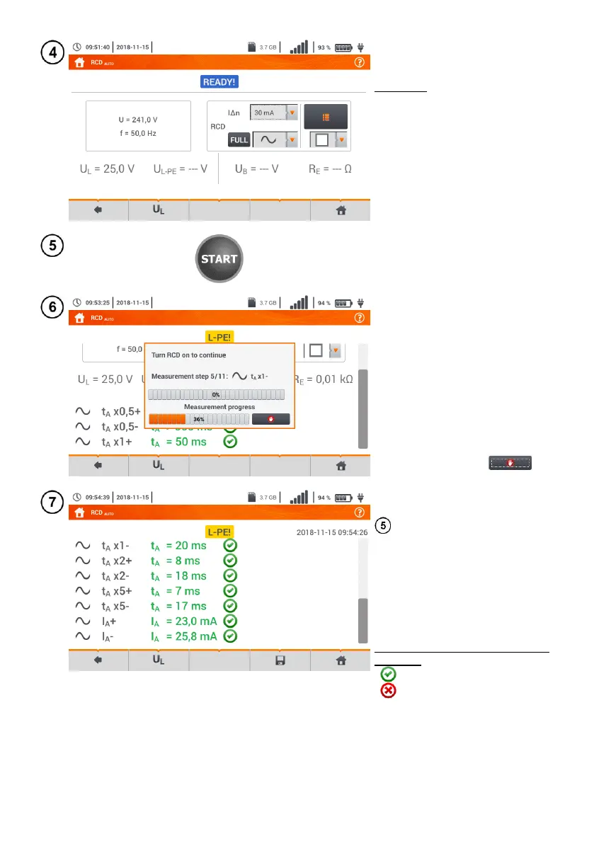
The meter is ready for measure-
ment.
Live mode
U – voltage between phase con-
ductor L and PE conductor
f – network frequency in the tested
circuit
Press START to start the meas-
urement.
Tested RCD switch, must be
turned on after each triggering,
measurements are completed.
The progress of the measurement
is illustrated by progress bars:
top – progress of the ongoing
measurement,
bottom – progress of the entire
measurement sequence.
The sequence may be cancelled
at any time using icon .
Eventually, measured parameters
are displayed (sec. 3.9.1 step
), and:
U
L
– test voltage,
U
L-PE
– voltage between L and PE,
U
B
– voltage measured on PE,
R
E
– PE continuity.
The list of results may be scrolled
on the screen.
Symbols indicating correctness of
response
criterion met
criterion not met
For more information refer to Cri-
teria for assessing the correct-
ness of component results.