Note
The fall prevention wire rope is designed to support the unit when suspended. Do not apply any load to it other than the load of
the unit.
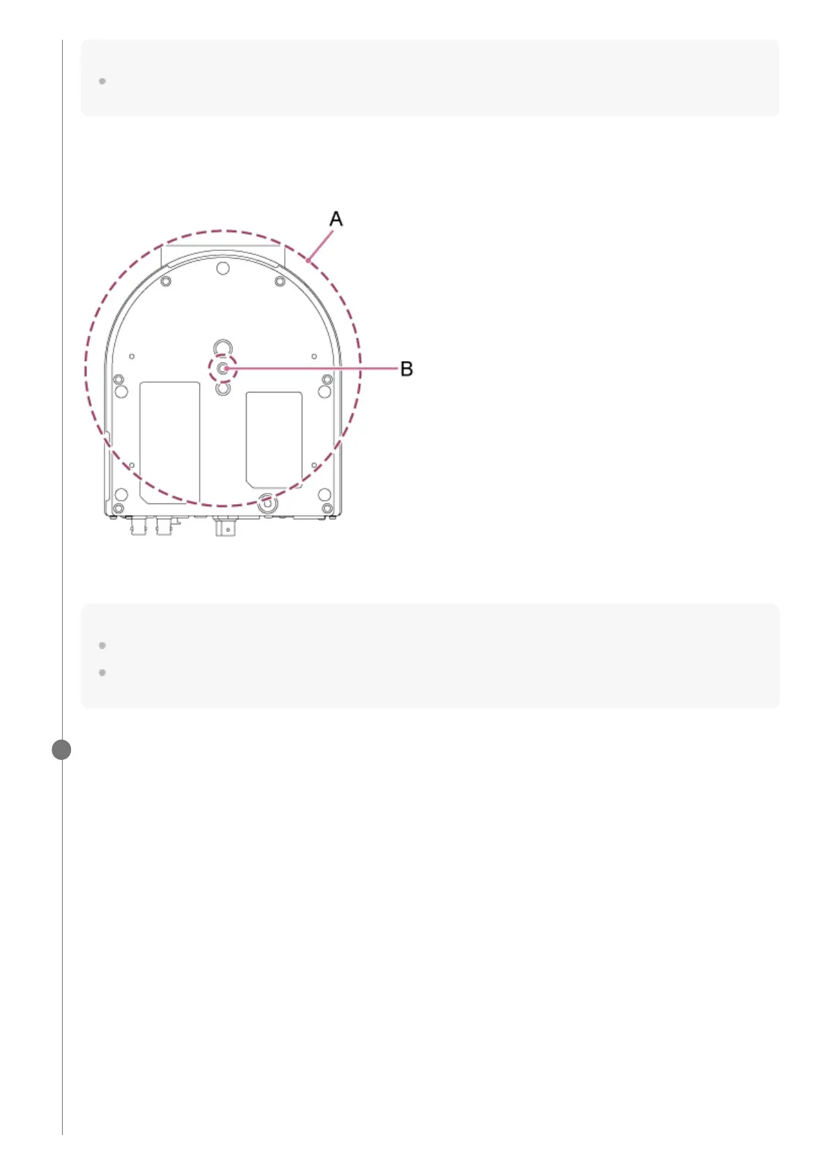
Mounting space
Refer to the following drawing when determining the mounting location and direction, taking into consideration the space
required for turning the lens and the wiring at the rear of the unit.
A: Camera head range of movement (ø199 mm)
B: Mounting wire rope feed hole (ø20 mm)
Note
Mount it in a stable location that is not subject to vibration. Locations subject to vibration may cause vibration in the image.
If the unit must be mounted on an inclined surface, keep it within ±15° of the horizontal and take measures to prevent the unit
from falling.
Attach the ceiling bracket (A) to the bottom of the unit using the four supplied screws (M3×8).
2
 Loading...