HCD-FL7D
3737
4. Mode: Record
5. Mode: Playback
6. Confirm the play back signal recorded in step 3 becomes ad-
justable level as follows.
If these levels are not adjustable level, adjust the RV53 (R-
CH) on the SP RELAY board to repeat steps 4 and 5.
Adjustable level:
CN804 PB level: 47.2 to 53.0 mV (–24.3 to –23.3 dB)
Adjustment Location: SP RELAY board
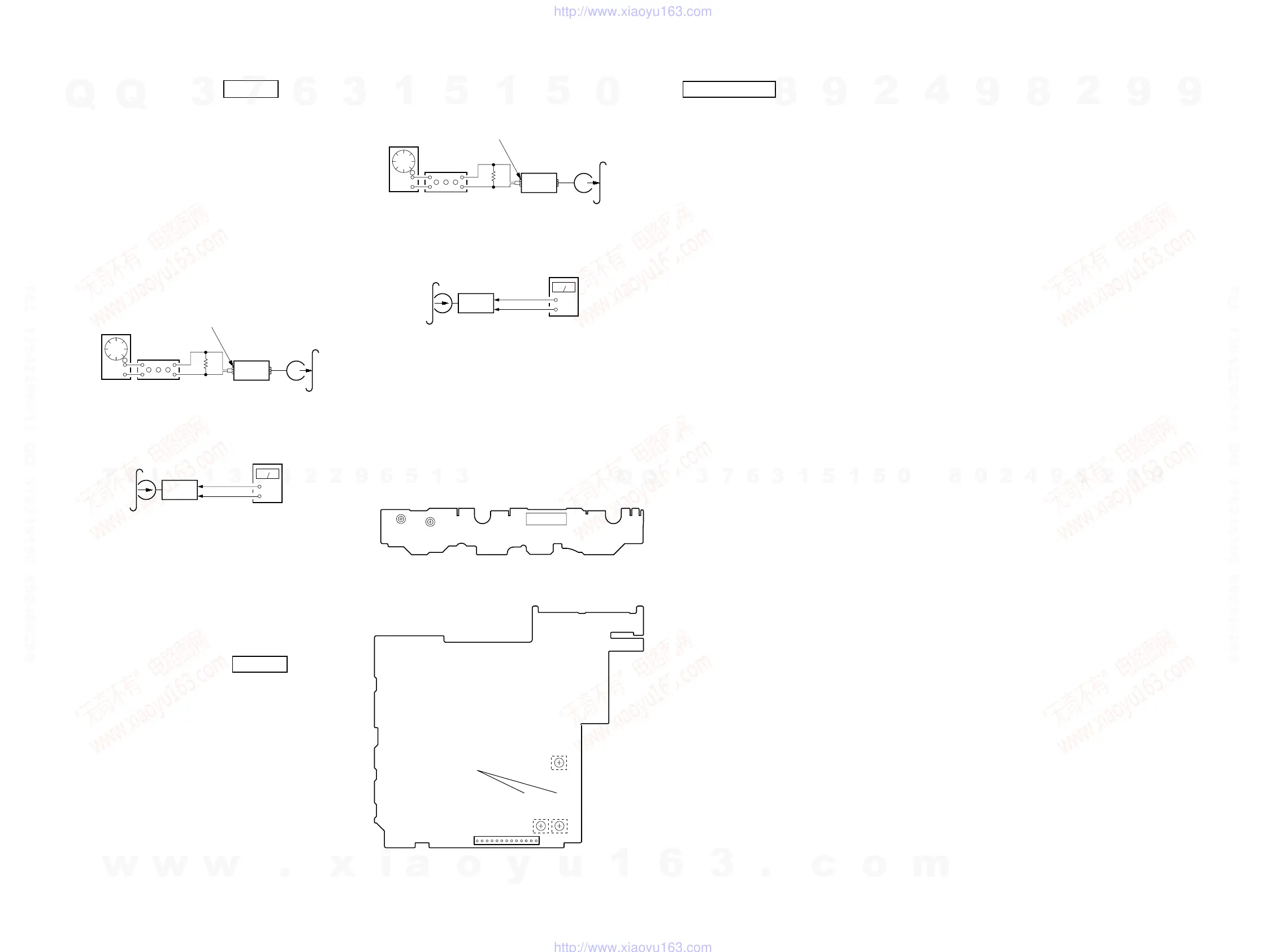
REC BIAS ADJUSTMENT DECK B
Procedure:
In the MC test mode, the “REC memory mode” is convenient for
this adjustment. In the “REC memory mode” , when the REC starts
the input signal FUNCTION is switched to VIDEO automatically.
When the REC stops, the tape returns near to the recording start
position.
1. Press [MD $VIDEO%] button to select VIDEO. (This step is not
necessary if the above test mode has already been set)
2. Insert a tape into deck B.
3. After press [REC PAUSE/START] button, press [REC
PAUSE/START] button, then rec ording start.
4. Mode: Record
5. Mode: Playback
6. Confirm the playback signal recorded in step 3 becomes ad-
justable level as follows.
If these levels are not adjustable level, adjust the RV2 (L-CH)
and RV52 (R-CH) on the SP RELAY board to repeat steps 4
and 5.
Adjustable level: Playback output of 315 Hz to playback output
of 10 kHz: ±1.0 dB
Adjustment Location: SP RELAY board
REC LEVEL ADJUSTMENT DECK B
Procedure:
In the MC test mode, the “REC memory mode” is convenient for
this adjustment. In the “REC memory mode” , when the REC starts
the input signal FUNCTION is switched to VIDEO automatically.
When the REC stops, the tape returns near to the recording start
position.
1. Press [MD $VIDEO%] button to select VIDEO. (This step is not
necessary if the above test mode has already been set)
2. Insert a tape into deck B.
3. After press [REC PAUSE/START] button, press [REC
PAUSE/START] button, then recording start.
attenuator
set
DSP board
MD (AUDIO) (J701)
1) 315 Hz
2) 10 kHz
50 mV (–23.8 dB)
600
Ω
blank tape
CN-123
AF OSC
+
–
set
recorded
portion
SP RELAY board
CN804 Pin
3
(GND)
SP RELAY board
CN804
Pin
2
(L-CH)
Pin
5
(R-CH)
level meter
set
DSP board
MD (VIDEO) (J701)
315 Hz, 50 mV (–23.8 dB)
blank tape
CS-123
600
Ω
attenuator
AF OSC
+
–
set
recorded
portion
SP RELAY board
CN804 Pin
3
(GND)
SP RELAY board
CN804
Pin
5
(R-CH)
level meter
TAPE SPEED
ADJUSTMENT
RV1002
RV1001
(NORMAL) (HIGH)
CN1001
– SW BOARD (Component Side) –
CN804
13
1
– SP RELAY BOARD (Conductor Side) –
REC BIAS
ADJUSTMENT
REC LEVEL
ADJUSTMENT
(L-CH)
(R-CH)
RV52
RV2
RV53
DVD SECTION
AUTO SERVO ADJUSTMENT
After parts related to the servo circuit (RF amplifier (IC001), DSP
(IC509), motor driver (IC501), EEPROM (IC903) so on) are re-
placed, re-adjusting the servo circuit is necessary. Select “ALL” at
“1. DRIVE AUTO ADJUSTMENT” (Refer to page 29 in TEST
MODE) and adjust DVD-SL (single layer), CD and DVD-DL (dual
layer).
Ver 1.3
w
w
w
.
x
i
a
o
y
u
1
6
3
.
c
o
m
Q
Q
3
7
6
3
1
5
1
5
0
9
9
2
8
9
4
2
9
8
T
E
L
1
3
9
4
2
2
9
6
5
1
3
9
9
2
8
9
4
2
9
8
0
5
1
5
1
3
6
7
3
Q
Q
TEL 13942296513 QQ 376315150 892498299
TEL 13942296513 QQ 376315150 892498299
http://www.xiaoyu163.com
http://www.xiaoyu163.com