98
Signal Selection
Chapter 3 Signal Selection and Transitions
a) To turn on the [DME1] to [DME4] buttons requires one of the [KEY1] to [KEY4] and [DSK1]
to [DKS4] buttons to be on.
Signal Assignment and Selection
Assigning signals to buttons
Each cross-point button has a button number, to which you assign a signal.
In addition to the signals input to the PRIMARY INPUTS 1 to 49 connectors
on the rear panel of the switcher, you can also select signals generated within
the switcher.
Each button has assigned to it a video signal and a key signal, forming a pair.
You can set these video and key combinations in a Setup menu.
Auxiliary
bus control
block
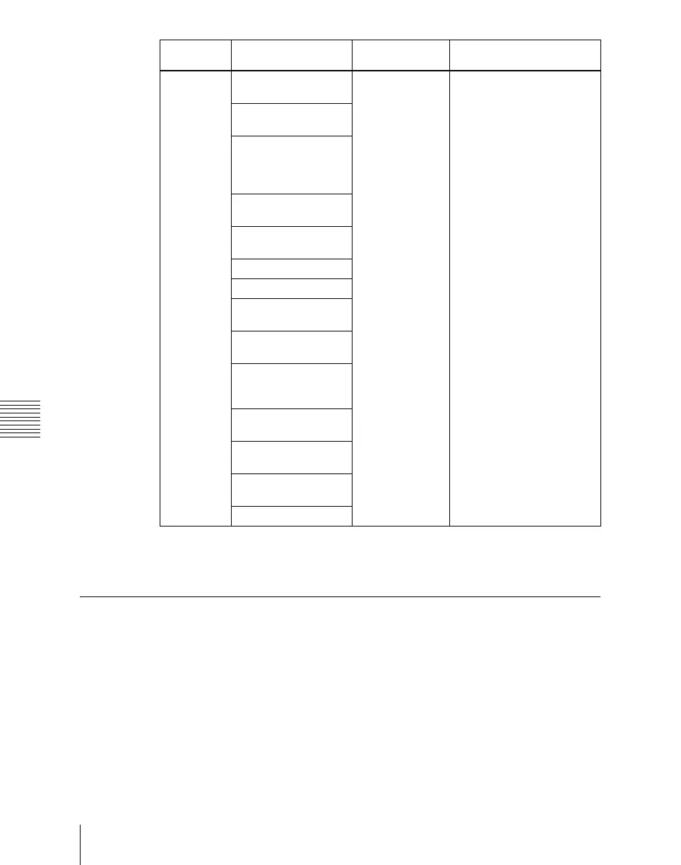
AUX1 to AUX48
buses
The key row of
the bank selected
with the bank
selection buttons
in the auxiliary
bus control block
Turn on the appropriate
buttons in accordance with
the signal assignment made
in the Setup menu.
MONITOR 1 to
MONITOR 8 buses
Frame memory
source 1 and frame
memory source 2
buses
DME 1 and DME 2
video buses
DME 1 and DME 2
key buses
Edit preview bus
M/E-1 UTILITY bus
P/P UTILITY 1 and P/
P UTILITY 2 buses
M/E-1 Key 1 fill to M/
E-1 Key 4 fill buses
M/E-1 Key 1 source to
M/E-1 Key 4 source
buses
DSK 1 fill to DSK 4 fill
buses
DSK 1 source to DSK
4 source buses
M/E-1 external DME
bus
P/P external DME bus
Bank Bus name Cross-point
button row
Delegation operation