18-2
SPINNER Werkzeugmaschinenfabrik GmbH
SM-1-03/02
18.1 Mikroskope
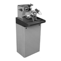
Figure 18-1: Microscope
Elements of the microscope:
A) Attaching block on the motor housing of Polyamid.
B) Attaching rail with lever 3 for the axial adjustment of the microscope
C) Rail for the radial adjustment of the microscope
D) Microscope support with 2 fixing levers
E) for radial adjustment
F) for the adjustment of height
G) Microscope unit
H) Adjustment ring
18.1.1 Axial adjustment of the microscope
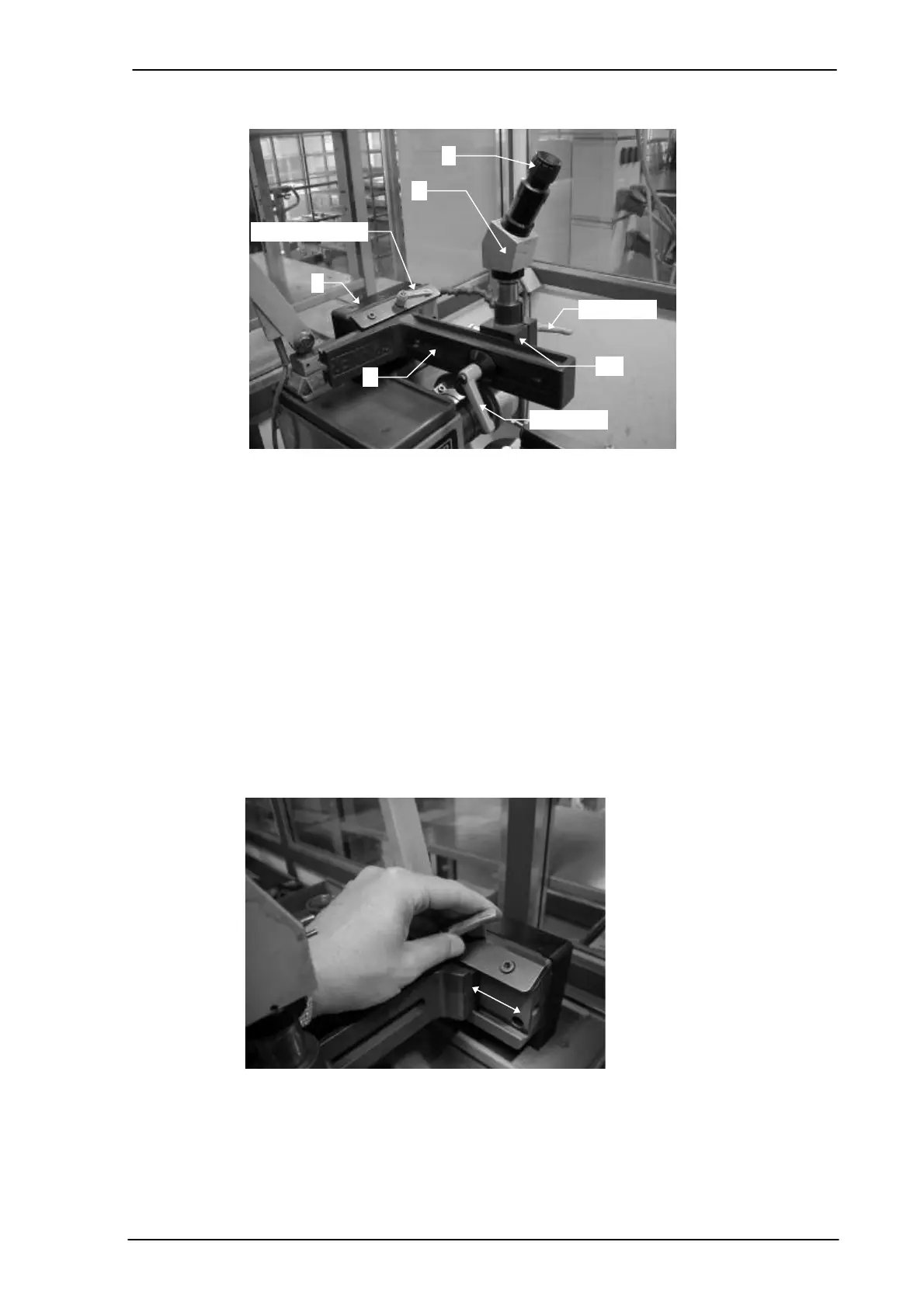
Figure 18-2: Axial adjustment of the microscope
For the optical viewing of the tool the microscope unit (components C, D, E) is inserted
into the fixing rail B and is shifted to the right and left until the edge of the tool can be
seen in the reticule of the microscope.
Once the right position is reached the unit is attached by means of the lever 3.