Connecting the Alarm Output
3.1.6.
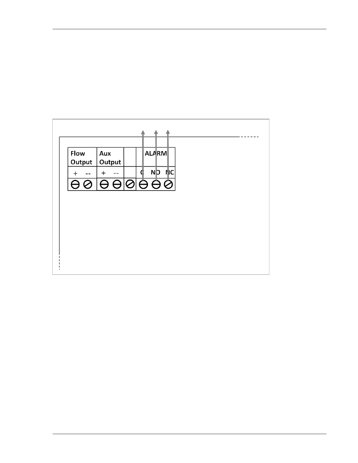
Connecting the Load Output
Using a flat head screwdriver, refer to the illustration below and to the Ranger Converter 3000 Installation
diagram at the end of this chapter for information on connecting the load output.
Flow Output: outputs the same frequency as sensor decoder 1.
Aux Output: outputs the same frequency as sensor decoder 2.
ALARM: controls dynamic load.
3000 Board