112/317
5 - Peripherals
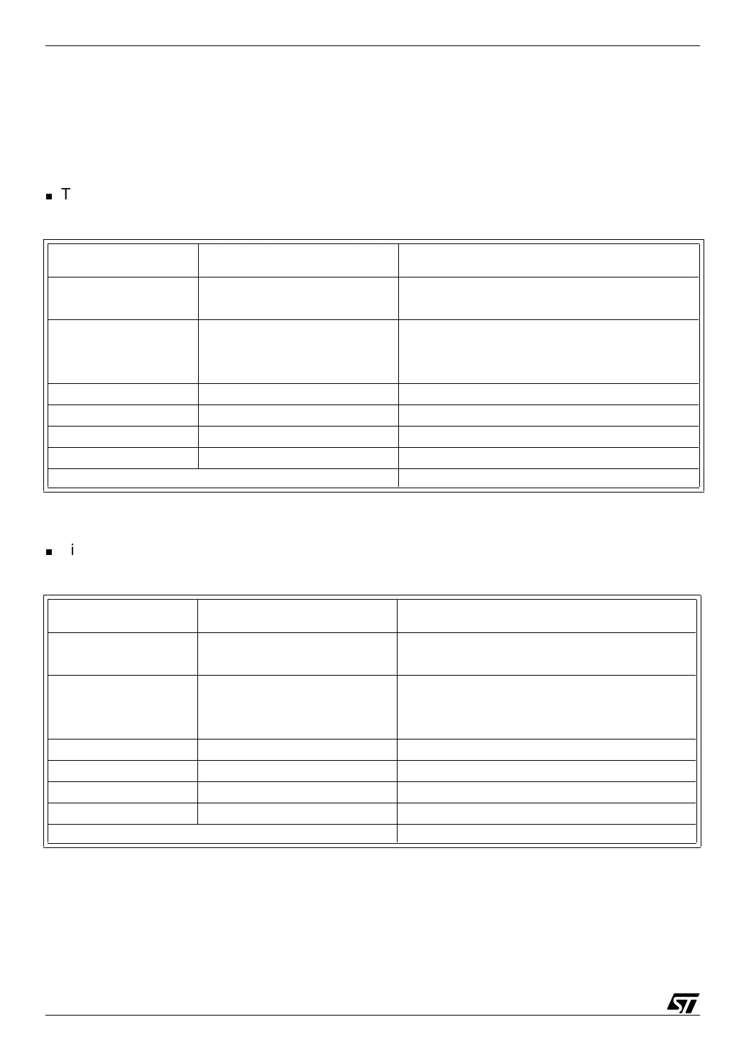
There are two such compare circuits for each free-running timer; the table below summarizes
the register, bit, and pin names for both timers A and B and for compare 1 and compare 2 cir-
cuits of each.
Timer A:
Timer B:
In the following text, we shall only consider the Output Compare 1 function of Timer A. The
other combinations are exactly the same, if the letters A, B and the figures 1, 2 are replaced
appropriately.
Channel 1 Channel 2 Function
TAOC1HR &
TAOC1LR
TAOC2HR & TAOC2LR
Output compare registers
(16-bit, read-write access)
OCMP1_A
PB1 on ST72251
PF4 on ST72311
OCMP2_A
PB3 on ST72251
doesn’t exist on ST72311
Output compare pins (1 and 2)
OCF1 OCF2 Output compare event flag (bit in TASR).
OC1E OC2E Output pin enable bit in TACR2.
OLVL1 OLVL2 Level to be output on compare (bit in TACR1).
FOLV1 FOLV2 Force compare bit in TACR1
OCIE Common Interrupt Mask Flag in TACR1
Channel 1 Channel 2 Function
TBOC1HR &
TBOC1LR
TBOC2HR & TBOC2LR
Output compare registers
(16-bit, read-write access)
OCMP1_B
PC1 on ST72251
PC1 on ST72311
OCMP2_B
PC4 on ST72251
PC0 on ST72311
Output compare pins (1 and 2)
OCF1 OCF2 Output compare event flag (bit in TBSR).
OC1E OC2E Output pin enable bit in TBCR2.
OLVL1 OLVL2 Level to be output on compare (bit in TBCR1).
FOLV1 FOLV2 Force compare bit in TBCR1
OCIE Common Interrupt Mask Flag in TBCR1