256/317
9 - A Carrier-current System for domestIc Remote Control
The PB1 pin is connected to the gate of a transistor that switches the 120 kHz oscillator on or
off. The output of this oscillator is amplified, and injected to the second pole of the line through
a capacitor.
The same pole of the line is used to detect the zero-crossing. To do this, it is connected to the
base of a transistor through a 1 Megohm resistor. A diode protects the base against the
voltage reversal. The collector is loaded by a 100 kOhm resistor, and this signal is fed to the
PB2 pin.
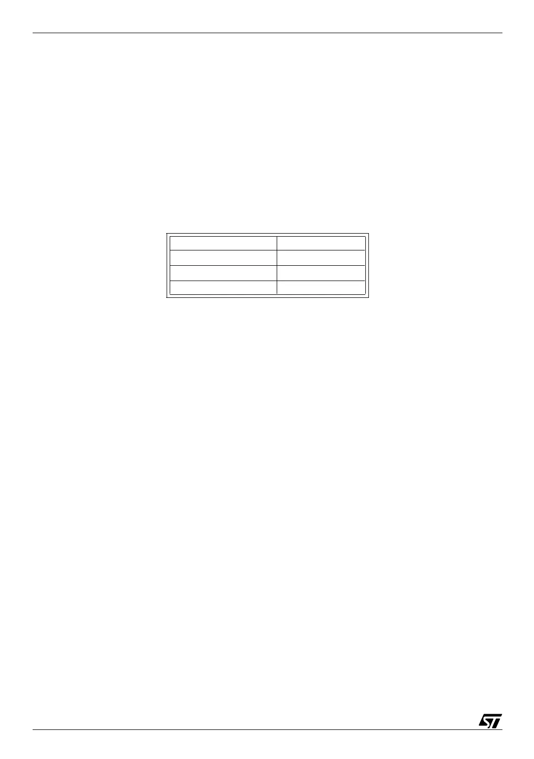
The three pushbuttons are connected to PB5 thru PB7, with a pull-up resistor, so that the pin
is pulled to the ground when the button is pressed.
The display is made of two one-digit, seven-segment LED devices. Each of the segments of
both devices are connected in parallel and to one pin of port A, and the common electrode of
each device is driven by a transistor, controlled by PA7. The drive circuit is arranged so that
when PA7 is high, one digit is lit; when low, the other digit is lit.
The House Code is set using a four-bit DIP switch that is fed to PC0 thru PC3.
Function Input number
OPEN PB5
CLOSE PB6
TIME PB7