275/317
9 - A Carrier-current System for domestIc Remote Control
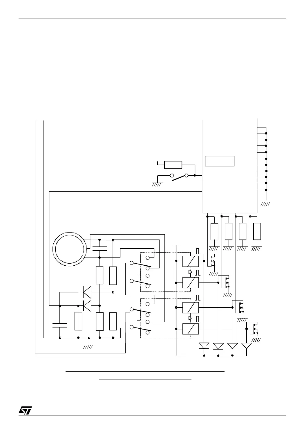
The four switches at the top select the House Code of the receiver. The receiver only obeys
the commands that are sent to its own House Code.
The power supply circuit looks like a classical Scheinkel voltage doubler. Actually, the input
capacitor (0.1 µF) presents a reactance that limits the current to about 7 mA RMS. Only half of
this current is rectified to charge the filtering capacitor (220 µF). The first diode both rectifies
the current and limits the voltage when blocked to 6.2 V. However, two diode drops should be
subtracted from that voltage, which produces a net voltage of about 5 V.
The filter has an adjustable resistor to tune its center frequency to that of the transmitter.
09-xr-2
1M
100nF
10K
10K
1M
1M
Va
Mot
1~
All diodes :
1N4148
Ph N
Pc0 (17)
(ana)
ST72E25
Carrier-current system : diagram of the receiver circuit ;
part 2 : the shutter motor control
Pb1 (10)
Manual
control
Va
100K
(15) Pc2
(14) Pc3
(13) Pc4
(12) Pc5
(11) Pb0
(8) Pb3
(25) Pa0
(24) Pa1
(23) Pa2
(22) Pa3
(26) Test
a
b
BS170
x4
V23042
SIEMENS
x2
Pb4 Pb5 Pb6 Pb7
(7) (6) (5) (4)
100K
100K
100K
100K