9.2 Power source selection
The STM32U5A9J-DK Discovery kit is designed to be powered by a 5 V DC power supply. It is possible to
configure the Discovery board with JP4 header to use any of the four sources described in Table 7 for the 5 V DC
power supply.
Table 7. 5V selection configuration jumper (JP4)
Reference
Jumper
(1)
Function Comment
JP4
STLK
5 V is supplied from USB STLK
CN5
• 5 V (+10%/-5%)
• 800 mA typ. embedded overcurrent protection
• Up to 500 mA capable
CHGR
5 V is supplied from USB STLK
CN5
• 5 V (+10%/-5%)
• No embedded current protection
• Up to 1.5 A current
USBC
5 V is supplied from the CN4
USB Type-C
®
connector
• 5 V (+10%/-5% at current < 500 mA)
• 5 V (+/-10% at current < 1.5A)
• No embedded current protection
• Up to 3 A (check USB Type-C® VBUS
constraints in that case)
E5V
5 V is supplied by the expansion
connector (CN9 5V_VIN and GND
pins)
• 5 V (+/-5%), up to 2 A
• No embedded current protection (can be
included on expansion add‑on board)
1. The default setting is in bold.
In all above four Power source configurations, the LED 5V (LD2) must be lit when the Discovery board is correctly
powered by the 5V supply.
The maximum recommended voltage applied on 5V in continuous mode must be 5.5 V in standard use cases.
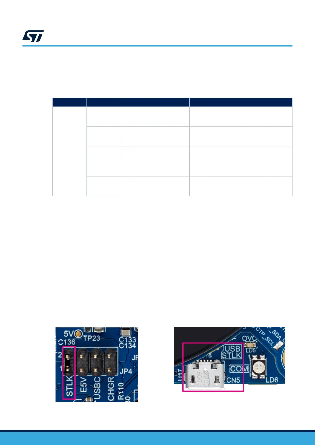
9.2.1 STLK (for compatibility with USB Host port legacy)
Figure 16 shows the selection of 5V from STLK on JP4, with a Power source connected to USB ST-LINK (CN5). It
is the default setting.
The USB ST-LINK CN5 connector can power the STM32U5A9J-DK Discovery kit, but the host PC only provides
100 mA to the ST-LINK circuit until the end of USB enumeration. At the end of the USB enumeration, the
STM32U5A9J-DK Discovery kit requires a 500 mA current from the host PC.
If the USB enumeration succeeds, an STMPS2151STR power switch èsupplies the board with up to 500 mA
current. This power switch also features an 800 mA current limitation to protect the PC in case of overcurrent on
the board.
Note: In this mode, in case a wall charger powers the board, there is no USB enumeration. Therefore, the COM LED
(LD6) blinks red, but the 800 mA protection is still active on the powered board.
Figure 16. STLK (JP4) from USB STLK (CN5)
DT56167V1
UM2967
Power source selection
UM2967 - Rev 1
page 20/68