14 Jumpers and solder bridges
14.1 Jumpers
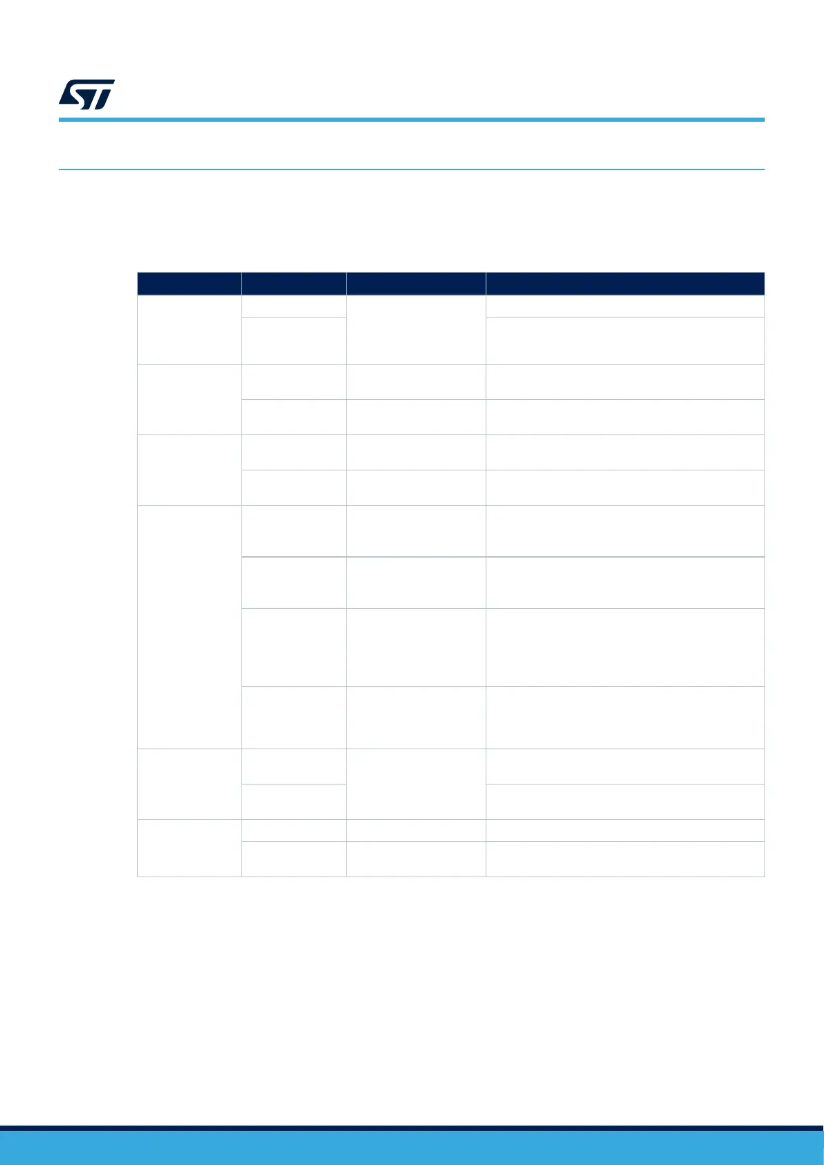
The jumper functions and their default status are described in Table 32.
Table 32. Jumper configuration
Reference
Jumper
(1)
Function Comment
JP1
ON 3V3 connected to SMPS
output
3V3 not connected to
SMPS output
SMPS powers 3V3. No Current measurement.
OFF
3V3 is not powered. Add an ammeter to power the
MCU and peripherals and measure the current.
JP2
ON
VDD connected to SMPS
output
SMPS powers VDD for peripherals. No Current
measurement.
OFF
VDD not connected to
SMPS output
VDD is not powered. Add an ammeter to power the
peripherals and measure the current.
JP3
ON
VDD_MCU connected to
SMPS output
SMPS powers VDD_MCU. No Current measurement.
OFF
VDD_MCU not connected
to SMPS output
VDD_MCU is not powered. Add an ammeter to power
the MCU and measure the current.
JP4
STLK
5 V is supplied by
USB STLK CN5
• 5 V (+10%/-5%),
• 800 mA typical overcurrent protection
• Up to 500 mA capable
CHGR
5 V is supplied by
USB STLK CN5
• 5 V (+10%/-5%)
• No embedded current protection
• Up to 1.5 A current
USBC
5 V is supplied by
USB Type-C
®
CN4 connector.
• 5 V (+10%/-5% at current < 500 mA), 5 V (+/-
10% at current < 1.5 A)
• No embedded current protection
• Up to 3 A (check USB Type-C® VBUS
constraints in that case)
E5V
5 V is supplied by
CN9 expansion connector
(5V_VIN and GND pins).
• 5 V (+/-5%), up to 2 A
• No embedded current protection (can be
included on expansion add‑on boards)
JP5
(2)
TNRST
ON
T_NRST
STLINK-V3E output reset connected to T_NRST of
STM32U5A9
OFF
STLINK-V3E output reset isolated from T_NRST of
STM32U5A9
JP6
(2)
STLK_NRST
OFF STLINK-V3E active STLINK-V3E detects USBSTLK plug on CN5
ON STLINK-V3E Reset state
Set STLINK-V3E in Reset mode (All IOs in high
impedance), no Power from JP4 STLK
1. The default setting is in bold.
2. JP5 and JP6 must not be ON together.
UM2967
Jumpers and solder bridges
UM2967 - Rev 1
page 49/68