12.1.3 2.47” display and DSI_V3 I/O interface
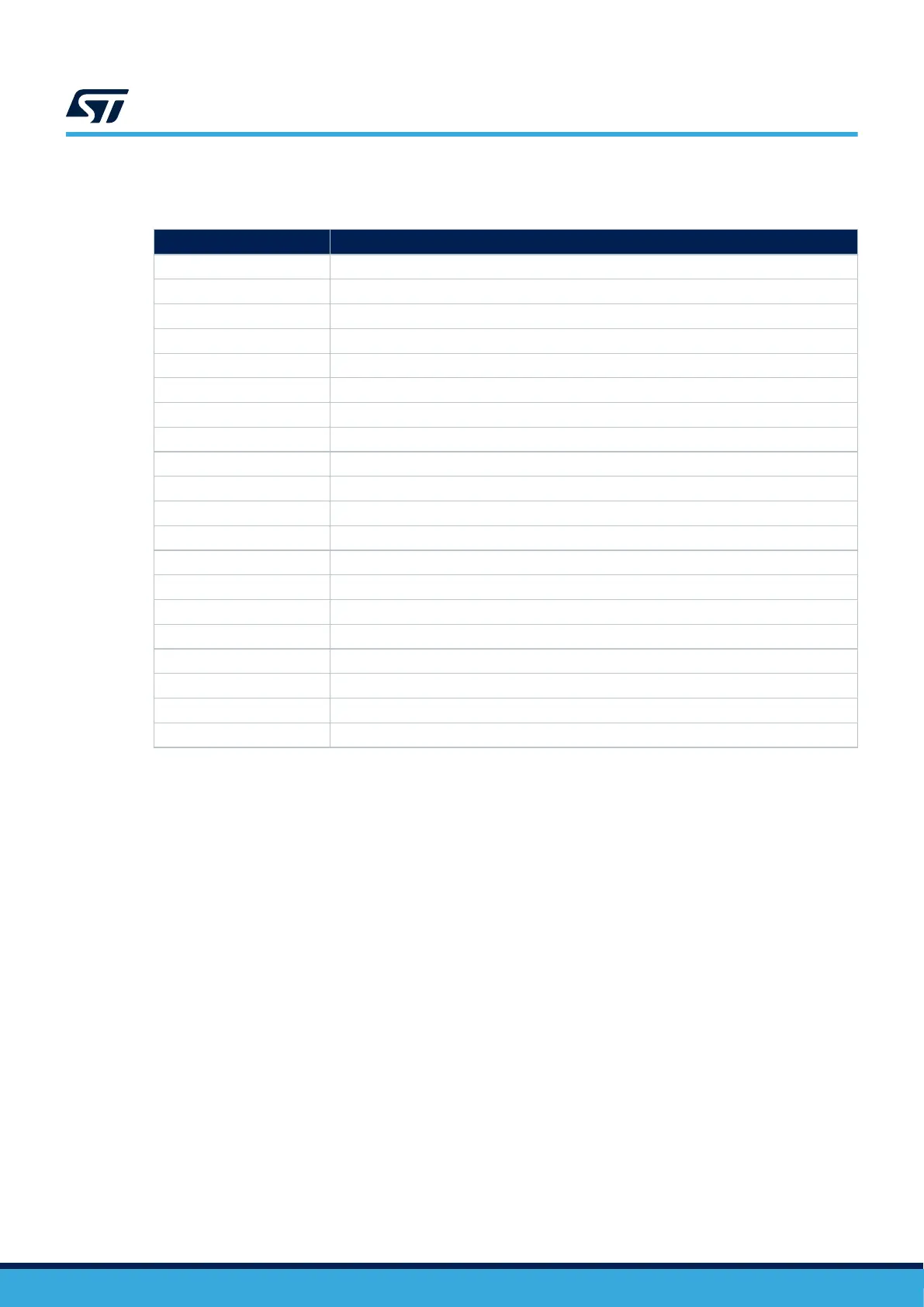
Table 9. 2.47” display and DSI_V3 I/O interface
PIO Configuration
PI6 BL_CTRL (DSI_BL_CTRL)
PD5 DSI_RESETn (DSI_RESETn)
PE8 TOUCH_INT (DSI_TOUCH_INT)
DSI_CKN CK_P (DSI.CK_P) – Polarity inversion on CN2 needs SW inversion on MCU.
DSI_CKP CK_N (DSI.CK_N) – Polarity inversion on CN2 needs SW inversion on MCU.
DSI_D0N D0_N (DSI.D0_N)
DSI_D0P D0_P (DSI.D0_P)
DSI_D1N D1_N (DSI.D1_N)
DSI_D1P D1_P (DSI.D1_P)
PH4 SCL (I2C5.SCL)
PH5 SDA (I2C5.SDA)
PI5 DSI_PWR_ON (DSI_PWR_ON) – not used
PD8 DSI_SPI_CS (DSI_SPI_USART_CS) – not used
PB13 DSI_SPI_CK (DSI_SPI_CLK) – not used
PD4 DSI_SPI_MOSI (DSI_SPI_MOSI) – not used
PD11 DSI_SPI_DCX (DSI_SPI_D/CX) – not used
PB10 USART3_TX (DSI_USART_TX) - not used
PD10 USART3_CK (DSI_USART_CK) – not used
PI7 SWIRE (DSI_SWIRE) – not used
PF11 TE (DSI_TE) – not used
12.1.4 Other DSI_V3 compatible peripherals
The MB1829 main board allows supporting the following peripherals (non-exhaustive list): MB1835B‑01,
MB1232A‑01 . Some peripherals require hardware adaptation (DSI_PWR_ON is not active by default):
• MB1829B-01 with MB1835B-01 (2.47” round LCD) uses default hardware configuration.
• MB1829B-01 with MB1232A-01 (HDMI board) needs hardware changes.
Updates with MB1232A-01 HDMI board:
• Remove R72 from the MB1829 (PIO is 5V‑tolerant. Ok to tie it to 3V3 on MB1232A side).
• Check SB53 is fitted on the MB1829 (or put a shunt on SB53, in case SB53 is formerly removed for
development purposes).
• Remove SB50 from MB1829 (to use pull-ups values on MB1232A side).
• Add 2.2 kΩ resistors on R8 and R9 of MB1232A.
• Add a 2.7 kΩ resistor on R5 of MB1232A.
• Use the free spacer/screw and pillar to attach MB1232A onto MB1829 for strong mechanical plugging.
Note: MB1232A-01 is part of B-LCDAD-HDMI1 product version 1.
UM2967
2.47” round TFT DSI display module board and DSI_V3 connector
UM2967 - Rev 1
page 28/68