12 Board functions
This section explains all the functions, peripherals, and interfaces of the board (refer to Section 1 Features,
Section 7 Hardware layout and configuration, Figure 5 and Figure 6 STM32U5A9J-DK top and bottom layout
views.
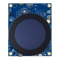
12.1 2.47” round TFT DSI display module board and DSI_V3 connector
Caution: • To peel off the LCD protective liner, do it slowly and carefully.
• If fixed patterns are displayed for a long time, a remnant image is likely to occur.
Note: The microcontroller software system must invert DSI.CK_N and DSI.CK_P lines together to align with DSI_V3
add-on boards. The DSI clock differential signals (_N and _P) are inverted on CN2 for layout reasons (refer to
DSI_V3 connector standard pinning in Section 13.4 DSI_V3 display board connector (CN2)).
Note: The MB1835 display module board is designed to be compatible with a VDD setting of 1.8 V. Refer to MB1835
schematics for more detailed constraints and options.
The LCD module supplier is Shenzhen Jinghua Displays Electronics Co., Ltd. (JHD), www.china-lcd.com website.
It is a 2.47” TFT round display, 480x480 resolution, 16.7 million color depth with a MIPI DSI
®
2‑lane interface
and a capacitive multi-touch panel, part number J025F1CN0201W or J025F1CN0201N. The STM32U5A9J-DK
Discovery kit integrates two DSI_V3 compatible connectors (refer to Section 13.4 DSI_V3 display board
connector (CN2) for details) to interface the main and LCD boards. The height between both boards is 8 mm.
12.1.1 Display management
The display is using a bi-directional two-data-lane DSI interface with one clock lane to interface with MB1829
main board. The DSI interface is used to transfer display and command data to the display controller (including
power‑saving modes and synchronization to avoid the tearing effect).
The MB1829 main board provides four power supplies to the MB1835 LCD module board. These power supplies
respect a power-up and power-down sequence following these timeframes:
• Power-up order (on 5V source activation): 5V_LCD -> 1V8_LCD -> VDD_LCD -> 3V3_LCD
• Power-down order (on 5V source removal): 5V_LCD -> 3V3_LCD -> 1V8_LCD -> VDD_LCD
Note: By default, 1V8_LCD is not used by MB1835. VDD_LCD is used instead of 1V8_LCD.
By default, the four power supplies are not switchable (power switches are replaced by 0 Ω solder bridges on
MB1829 main board).
The PIO list description of the DSI_V3 connector and the default PIO configuration is defined in
Section 12.1.3 2.47” display and DSI_V3 I/O interface. Many PIOs are not used by default, refer to the I/O
interface table.
Some PIOs are used by default to manage the LCD screen display (for dedicated touch-panel PIOs, refer to
Section 12.1.2 Touch-panel management):
• DSI_RESETn (PD5, active Low), to control the HW RESET (common control with the touch panel)
• DSI_BL_CTRL (PI6, active high), to control the Backlight (PIO, PWM, or SWIRE modes are possible)
Refer to the “Reset timing” and “Power on/off sequence and timing” sections of the display controller datasheet or
touch-panel datasheet for further DSI_RESETn management details.
DSI_TE PIO (PF11) is not used by default. It might be used with other LCD module boards to manage the tearing
effect function and synchronize host frame writing with the display controller.
12.1.2 Touch-panel management
The capacitive touch panel is driven through the I2C5 microcontroller interface (up to 400 kHz). The I
2
C read/write
address is 0xE1/0xE0.
The DSI_RESETn PIO (PD5, active low) controls the touch-panel controller hardware reset, at the same time as
the display reset, but each reset signal is adapted to the peripheral (thanks to level shifters on MB1835). Pay
attention to respect hardware reset timings depending on the used LCD module board.
The DSI_TOUCH_INT PIO (PE8, active low) manages the touchscreen interrupt function, to synchronize touch-
panel activation with Host. It might also wake up the MCU from standby/shutdown modes.
UM2967
Board functions
UM2967 - Rev 1
page 27/68

 Loading...