Pin
Pin
name:
marking
Signal
description
STM32
pin
MCU function Pin
Pin
name/
marking
Signal
description
STM32
pin
MCU
function
11 PD9 SAI2_MCLK PD9 SAI2 12 PG10 SPI3_MISO PG10 SPI3
9 PD12 SAI2_FS PD12 SAI2 10 PG9 SPI3_SCK PG9 SPI3
7 PE4 SAI1_FS PE4 SAI1 8 GND GND - -
5 PE5 SAI1_SCK PE5 SAI1 6 VREFP VREFP VREFP VREF+
3 PE6 SAI1_SD_A PE6 SAI1 4 PG13 I2C1_SDA PG13 I2C1
1 PE2 SAI1_MCLK PE2 SAI1 2 PG14 I2C1_SCL PG14 I2C1
Note: Pins 21 and 22 are free of use.
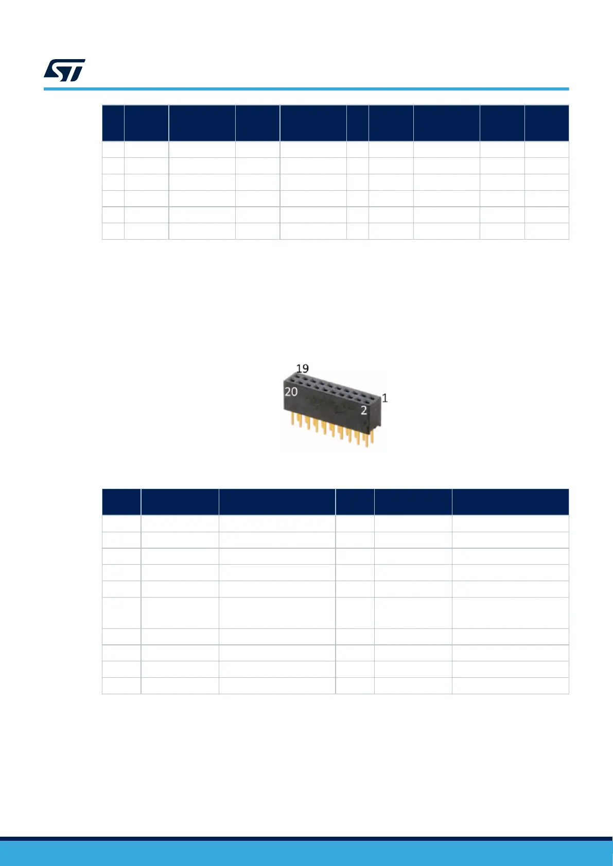
13.8 20‑pin audio connector (not used) (CN1)
Note: The 20
‑
pin audio connector function (Audio MEMs) is not present by default.
The 20‑pin audio connector allows connecting ADF or MDF audio MEMS add-on boards.
Figure 33. 20‑pin audio connector (CN1)
Table 31. 20‑pin audio connector pinout (CN1)
Pin
number
Description Assignment
Pin
number
Description Assignment
1 GND Ground 2 VDD VDD (1.8V)
3 - - 4 CCK0 MIC.CCK0 (PF3)
5 SDIN4 MIC.SDIN4 (PE10) 6 SDIN0 MIC.SDIN0 (PF4)
7 - - 8 - -
9 - - 10 - -
11 - - 12 MEMS_LED (3.3V)
Audio_MEMs_LED
(PE13)
13 - - 14 - -
15 - - 16 - -
17 - - 18 - -
19 VDD VDD (1.8V) 20 GND Ground
UM2967
20‑pin audio connector (not used) (CN1)
UM2967 - Rev 1
page 48/68