11 Boot options
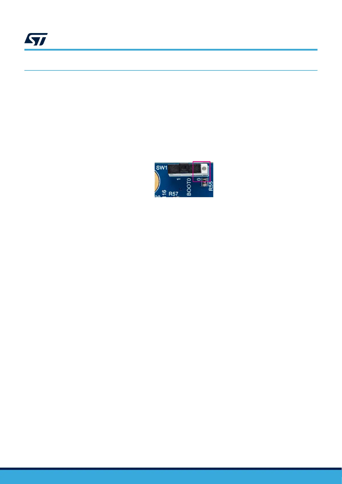
Attention: The white side of the SW1 switch indicates the Boot0 value setting (default position white switch at the right
indicates BOOT0 = 0), refer to Figure 21.
By default, the boot procedure is managed through the PH3/BOOT0 pin of MCU (center pin of BOOT0 SW1
switch). The PH3/BOOT0 pin is connected either to a 10 kΩ pull-down (position 0) or to a 10 kΩ pull-up (position
1).
As the nSWBOOT0 option bit of STM32U5A9NJH6Q is set to 1, STM32U5A9J-DK boots on internal flash
memory, thanks to the SW1 switch default position (BOOT0 = 0).
SW1 is located on the bottom side of the board due to mechanical constraints. For specific purposes, the switch
might be moved on top when CN1 is not used or replaced with a standard 3-pole header with a jumper.
Figure 21. BOOT0 default configuration, set on “0” (SW1)
DT56173V1
UM2967
Boot options
UM2967 - Rev 1
page 26/68