The embedded footprint is also compatible with other eMMC references in the 153‑ball package, check the
compatibility of the memory datasheet versus MB1829 schematics.
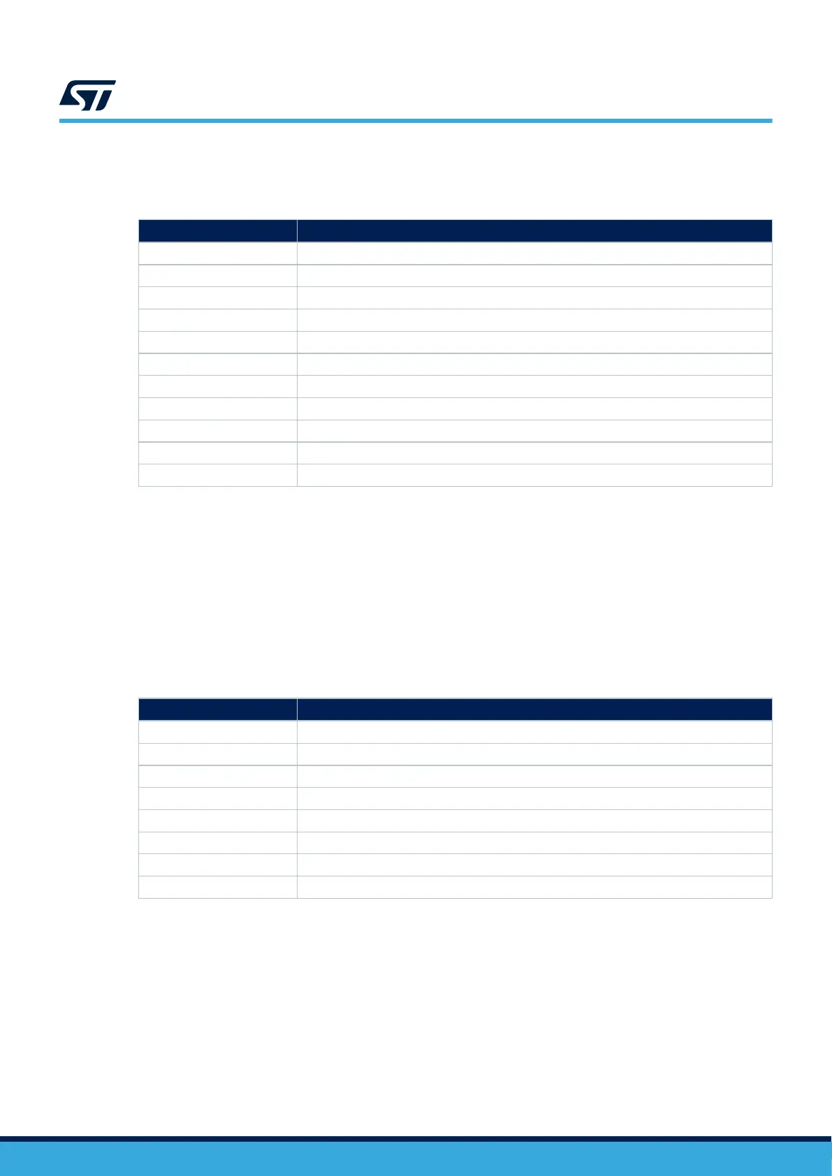
Table 14. eMMC flash I/O interface
PIO Configuration
PD2 CMD (SDMMC1.CMD)
PC12 CLK (SDMMC1.CK)
PC8 D0 (SDMMC1.D0)
PC9 D1 (SDMMC1.D1)
PC10 D2 (SDMMC1.D2)
PC11 D3 (SDMMC1.D3)
PB8 D4 (SDMMC1.D4)
PB9 D5 (SDMMC1.D5)
PC6 D6 (SDMMC1.D6)
PC7 D7 (SDMMC1.D7)
PH6 eMMC_RSTn (eMMC.RSTn)
12.6 Audio codec (not used)
Note: SAI audio codec (U5) and audio jack (CN6) functions are not populated by default.
STM32U5A9J-DK features a CS42L51-CNZ audio codec with an SAI interface and with a 3.5 mm audio jack
connector (for stereo output and analog microphone). For the audio jack description, refer to the connector
section.
The audio codec is driven through the I2C4 interface (100 kHz). The I
2
C read/write address is 0x95/0x94. An SAI
5-wire interface transfers audio PCM data. A dedicated PIO (Audio_RSTn, PH2, active low) is used to reset the
audio codec.
Table 15. Audio codec I/O interface
PIO
Configuration
PB7 SDA (I2C4.SDA)
PB6 SCL (I2C4.SCL)
PE5 SCK_A (SAI1.SCK_A)
PE4 FS_A (SAI1.FS_A)
PE6 SD_A (SAI1.SD_A)
PE3 SD_B (SAI1.SD_B)
PE2 MCLK_A (SAI1.MCLK_A)
PH2 Audio_RSTn (RESETN)
12.7 20‑pin audio connector (not used)
Note: The audio 20-pin connector function (CN1, audio MEMS) is not populated by default.
STM32U5A9J-DK features a 20‑pin audio connector (CN1) to interface audio MEMS microphones on add‑on
boards. MDF and ADF interfaces are available through one clock and two data wires. PE10, PF4, and PF3 PIOs
can manage up to four MEMS microphones. PE13 (Audio_MEMS_LED) is a control PIO to light a LED.
UM2967
Audio codec (not used)
UM2967 - Rev 1
page 33/68