Table 23. MIPI10 on STDC14 footprint
Pin
number
Description Signal assignment
Pin
number
Description Signal assignment
1 - - 2 - -
3 VDD power VDD (1.8 V) 4 SWDIO/JTMS T.SWDIO (PA13)
5 GND GND 6 SWCLK/JTCK T.SWCLK (PA14)
7 KEY GND 8 SWO/JTDO T.SWO (PB3)
9 - - 10 JTDI T.JTDI (PA15)
11 GNDDetect 100 Ω pull-down 12 RESET T_NRST (PG10)
13 - - 14 - -
Note: Pins 1, 2, 13, and 14 belong to the STDC14 footprint and are not accessible with a MIPI10 compatible probe.
13.2.2 STDC14 debug connector (option)
The STDC14 debug connector might be implemented, depending on supported tools, for easy interface with ST
tools ecosystem.
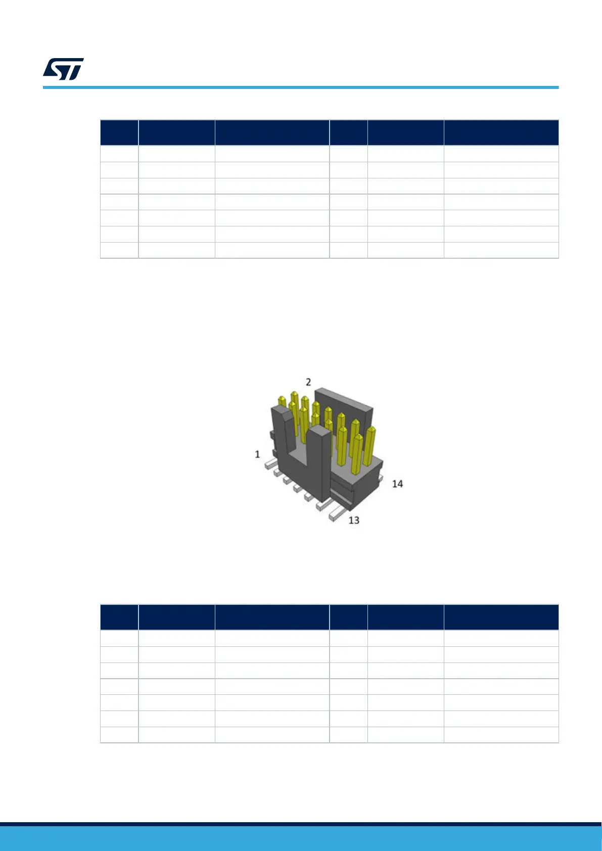
Figure 26. STDC14 debug connector (CN11)
DT52375V1
If needed, a MIPI10 compatible probe can be plugged into the STDC14 connector (CN11) but you might have to
bend or cut pins 1, 2, 13, and 14.
Table 24. STDC14 connector pinout
Pin
number
Description Signal assignment
Pin
number
Description Signal assignment
1 - - 2 - -
3 VDD power VDD (1.8V) 4 SWDIO/JTMS T.SWDIO (PA13)
5 GND GND 6 SWCLK/JTCK T.SWCLK (PA14)
7 KEY GND 8 SWO/JTDO T.SWO (PB3)
9 - - 10 JTDI T.JTDI (PA15)
11 GNDDetect 100 Ω pull-down 12 RESET T.NRST (PG10)
13 RX USART1_RX (PA10) 14 TX USART1_TX (PA9)
Note: USART1_RX and USART1_TX are signals from STM32U5A9NJ.
UM2967
Debug connector (CN11)
UM2967 - Rev 1
page 41/68