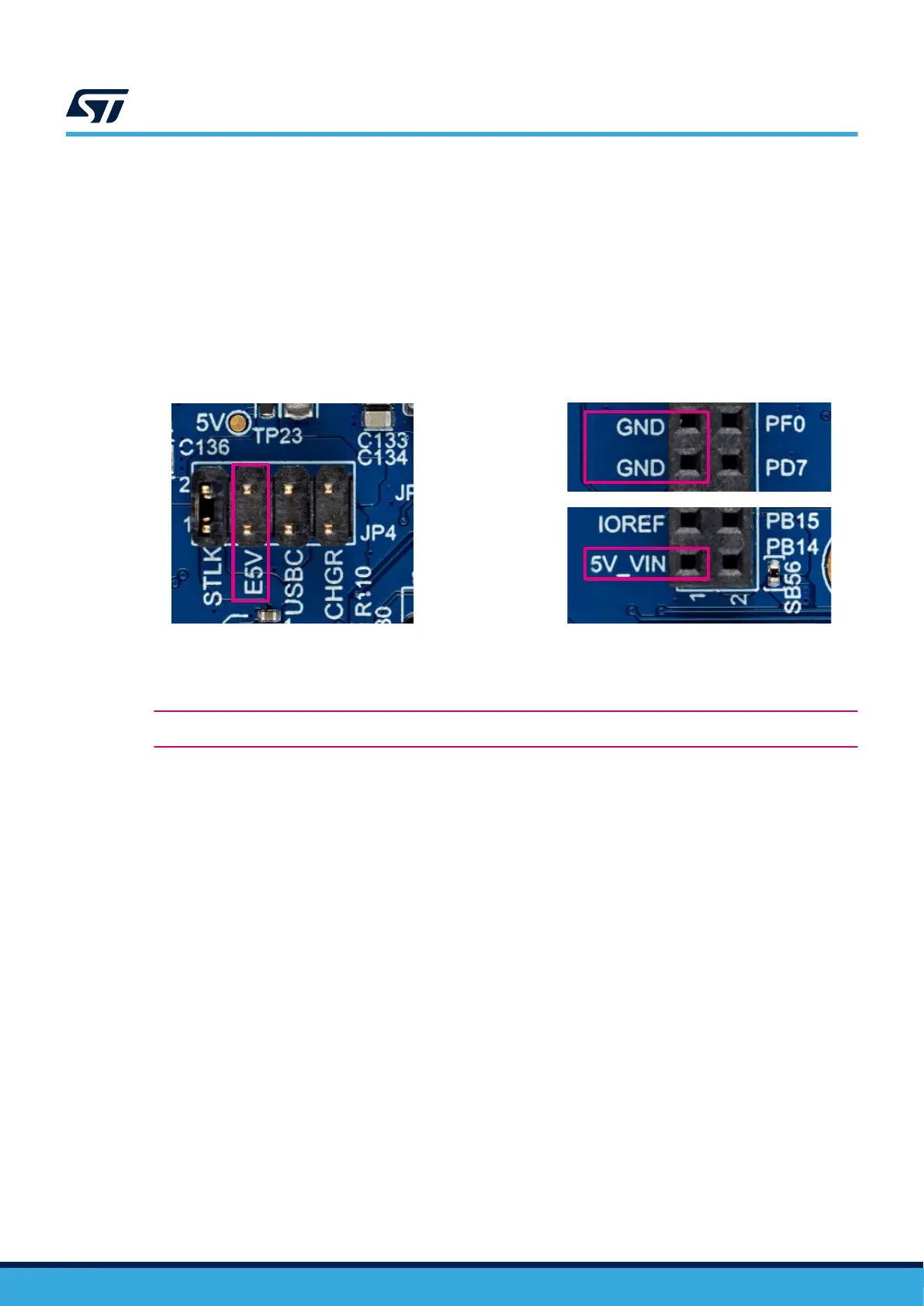
9.2.4 E5V
Figure 19 shows the selection of 5 V DC power from E5V on JP4, with a Power source connected to external
5V_VIN pin 1 (CN9) and GND pin 11 or 13 (CN9). Note that GND pins are also available on other pins
of expansion connectors (CN9 and CN10). Refer to Section 13.7 Expansion connectors (CN9 and CN10)
for details. In this case, the STM32U5A9J-DK Discovery kit must be powered by a power supply unit or
auxiliary equipment complying with standard EN 60950-1: 2006+A11/2009+A12/2011+A2/2013 or EN 62368-1
(2014+A11/2017), and must be Safety Extra Low Voltage (SELV/ES1) with limited power capability (LPS/PS2).
Note: There is no input current protection on MB1829 in this configuration. The recommended maximum current to be
drawn from this E5V pin is 1.5 A, but 2 A must also be functional in practice (current protection might be placed
on the expansion board).
Figure 19. E5V (JP4) from 5V_IN/GND (CN9)
DT56171V1
9.3 Microcontroller power
Warning: This Discovery kit is a low
‑
power system designed for VDD and VDD_MCU at 1.8 V only.
Attention: Do not remove the JP3 header when the board is powered up, or do not start the board with JP3 OFF, this might
have an impact on the long
‑
term reliability of the MCU in specific temperature conditions. Use preferably JP4
removal or the reset button or Power source removal to restart the board.
Attention: Do not remove the JP2 header when the board is powered up, it might have an impact on the long
‑
term
reliability of the peripherals.
Attention: This Discovery kit uses a power scheme that might be different from standard application notes, refer to relevant
application notes for your design.
By default, the STM32U5A9NJH6Q microcontroller power supply pins are connected to the VDD_MCU power
supply (1.8 V) and the 3V3 power supply (3.3 V). In case the user wants to test any other power supply
configuration, a few solder bridges can be modified (refer to Section 14.2 Solder bridges).
Two TPS62140 SMPS devices supply the 1.8 V and the 3.3 V power supplies of the board (going to the
microcontroller and peripherals). Both SMPS outputs can supply a current of 1 A. The three headers (JP1, JP2,
and JP3) allow measuring the currents going respectively to:
• IDD 3V3 (JP1): Current from 3V3_SMPS to 3V3 power supply (VDDUSB of MCU and 3V3 of peripherals)
• IDD (JP2): Current from VDDMCU_SMPS to VDD peripheral power supply (VDD is going only to
peripherals)
• IDD MCU (JP3): Current from VDDMCU_SMPS to VDD_MCU (only to the MCU)
UM2967
Microcontroller power
UM2967 - Rev 1
page 22/68